DYNAMOMETER-TYPE METERS
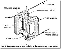
The previously described instruments are suitable for measurements of de only, because the field supplied by the permanent magnet is unidirectional. If the permanent magnet is replaced with stationary coils arranged as shown in Fig. 8, and the moving and stationary coils are connected in series, the moving coil will be deflected by an alternating current. This deflection is obtained because, when the alternating current reverses, the current in the fixed and moving coils reverses at the same instant, resulting in a pulsating torque which is always in the same direction. The amount of deflection depends directly on the amount of alternating current flowing through the coil system.
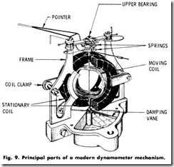
The principle of operation of this type of meter has resulted in the design of the modern dynamometer instrument shown in Fig. 9. Regardless of the degree of refinement used in the construction of this instrument, however, it takes a considerably larger amount of current than the permanent-magnet type employed for direct-current measure ment. Here, the current being measured must not only supply the energy for the moving coil, but must also supply energy for the field winding, which in the case of the permanent-magnet instrument was supplied by the magnet.
Another important consideration in connection with this type of instrument is to keep masses of metals, as well as closed loops of wire, away from the instrument coil system. Any such material would form a path in which current could be induced, thus causing reading errors when used for ac measurements.
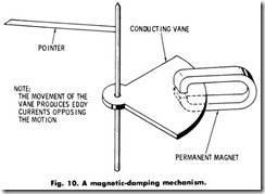
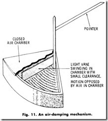
Because of the oscillating effect of the alternating current on the instrument pointer, the instrument is equipped with a damper. This damping is accomplished in one of two ways, either (a) by the use of a thin aluminum or copper vane which swings between the poles of a permanent magnet, or (b) by the use of a closed box in which a vane swings in a restricted space.
The first method is called magnetic damping (Fig. 10), and the second is called air damping (Fig. 11). Both methods are in common use, although it is considerably easier to obtain high values of damping by the magnetic method.
Voltmeters
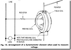
If a suitable series resistance constructed of zero-temperature coeffi cient material is added to this type of instrument, as shown in Fig. 12, then it can be used to measure ac voltage. Ac voltmeters draw considerably more current from the line than de voltmeters. In fact, it is not unusual to have a high-grade portable ac voltmeter of a 150-volt rating that requires as much as 75 milliamperes for full-scale deflection. This gives an instrument resistance of approximately 2000 ohms and a full-scale power consumption of about 11 watts.
The series resistor in Fig. 12 contributes nothing to the torque of the instrument, since the torque is governed by the product of the ampere turns of the fixed and moving coils. If the fixed and moving coils were to be wound entirely of resistance wire, the fixed resistor normally used could be dispensed with. This, however, is not practical because of the large amount of heat which would then have to be dissipated by the coil system.
To dispose of this difficulty , the fixed and moving coils are wound with copper wire. Then, to reduce the instrument error caused by the change in the resistance of copper when the temperature is varied, it is customary to mask, or “swamp out,” the error by using sufficient series resistance of negligible temperature coefficient. It has been found that a satisfactory relation between copper resistance and swamping resistance exists when the copper resistance amounts to about 10% of the total resistance of the instrument. In other words, in the 150-volt portable instrument previously described, the field and moving coils would have a combined resistance of about 200 ohms, and the series resistance would be approximate}y 1800 ohms, making a total of 2000 ohms.
If the full-scale voltage rating of the instrument is lowered, the resistance of the instrument, of course, must decrease. Also, it is necessary to keep the copper resistance at about the same proportion namely I0%. This limits the number of turns which it is possible to wind on the fixed and moving coils. Hence, to get the same torque in the instrument, more current must be used, which means that the instrument may draw a very appreciable amount of current from the line. For example, a 15-volt ac instrument of the higher-grade portable type may draw as much as 250 milliamperes from the line.
To illustrate the effect of increasing the percentage of copper resis tance, an instrument could be made which would require less current for full-scale deflection by using a smaller size of copper wire on the fixed and moving coils, and by increasing the number of turns. However, the performance of the instrument under various conditions of ambient temperature might be quite poor.
Suppose that, instead of using 10% or 6 ohms of copper in a 15-volt,60-ohm instrument, 30 ohms of copper and 30 ohms of zero tempera ture coefficient resistance were used. Copper changes 0.4% for each degree C change in ambient temperature-thus, if the temperature at which the instrument is used were increased 10%, the resistance of the copper circuit would increase to 31.2 ohms, giving an instrument resistance of 61.2 ohms at this temperature. The instrument would then read 60/61.2 or only 98% of the correct value, when 15 volts were applied.
The foregoing assumption as to instrument indication does not take into account the change in elastic modulus of the instrument springs at this higher temperature. As a matter of fact, in most instruments, the elastic property of the phosphor-bronze spring material changes in such a direction as to compensate partly for the error in indication caused by the change in the copper resistance of the instrument.
Ammeters
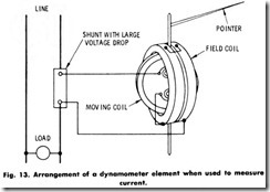
Instead of changing the milliammeter into a voltmeter by providing it with a series resistance, it can be used to measure higher values of alternating current by equipping it with a shunt. However, there would be some practical difficulties in applying this scheme if the shunt were connected as shown in Fig. 13. The shunt would have to have a very high voltage drop at the rated current to divert sufficient current through the ammeter element to obtain full-scale deflection. The meter element would also have to consist principally of copper. As the ambient temperature increased, the amount of current flowing in the instrument element for any given line current would be lower. The inductance of the coils must also be considered.
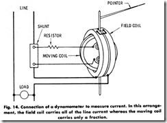
In order to overcome these difficulties, it is customary to send the full line current through the fixed coils of the meter and to allow only the current for the moving element to be taken off the shunt, as shown in Fig. 14. This arrangement permits the use of some series resistance and materially improves both the temperature coefficient and the time constant of the instrument. For lower ratings, the shunt can be located within the instrument case.
Wattmeters
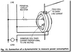
Assume the ammeter arrangement shown in Fig. 14 is connected as shown in Fig. 15, omitting the shunt and adding resistance in series with the moving element instead. On alternating current, the deflection of the instrument pointer would depend on the product of the instantaneous current flowing in the fixed and moving coMs. Since the current in the moving element is proportional to the line voltage, the instrument indication will be proportional to the product of the instantaneous voltage times the instantaneous line current. In other words, the instrument will read watts, and the scale can be so marked.
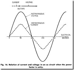
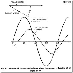
If the maximum and other corresponding values of current and voltage occur at the same instant, as shown in Fig. 16, the load is said to have a power factor of unity, since cosine cP (cP is the angle between current and voltage) is equal to 1 . If the current lags 30° behind the voltage, as in Fig. 17, the power factor is 0.866 lagging.
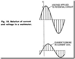
Note how the instrument in Fig. 15 will respond to this condition, remembering that it always reads the quantity proportional to the instantaneous product of the volts and amperes. To take a specific example: Draw lines corresponding to the voltage and current (values e and i) at a given instant, t, as shown in Fig. 18, and take their product.
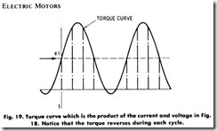
This product (e x i in Fig. 19) will be indicative of the torque on themoving element at that particular instant. Repeating this at suitable intervals, a torque curve which approximates that shown in Fig. 19 will be obtained.
Note that the torque is positive in direction at certain intervals during the cycle, and negative in others. The instrument pointer will, of course, assume a position dependent on the average value of the torque over a period of time, since the instrument element is not light enough to respond to each impulse of a 60-hertz source. Had a power factor of unity been selected, the torque would have been positive in direction at every instant.
While pursuing this analysis, apply it to the voltmeter (which would be connected across the same line), plotting the torque curve over one cycle. Since, in a voltmeter the field and moving coils are connected in series, the instantaneous currents in each element are always in phase, regardless of the power factor of the line. To obtain the torque curve, simply square the ordinates on the current curve. Because of the mass of the moving element, the instrument pointer will again assume an average position with respect to the double-frequency torque pulsations. These conditions and the procedure are indicated in Fig. 20.
The dynamometer-ammeter element that was shown in Fig. 15 will also be subjected to the same continuous positive pulsating torque, since the current in the movable coil is always in phase with the line current which flows in the current coil.
It should always be remembered that:
1 . The dynamometer voltmeter indicates root-mean-square (rms) voltage.
2. The dynamometer ammeter indicates root-mean-square (rms) current.
3. The dynamometer wattmeter indicates average power.
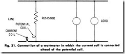
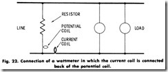
A wattmeter may be connected in a circuit as shown in Fig. 21 or as in Fig. 22. Note that, in one case, the wattmeter potential-circuit loss is being measured, and in the other case, the current-coil loss. The potential-circuit loss of a typical portable 500-watt wattmeter would be in the order of 2 watts at 100 volts. Hence, if this instrument were connected as in Fig. 21, the reading would be 2 watts higher than the true value consumed in the load. The current coil for this particular wattmeter requires about 2 watts at about 5 amperes. Since the voltage is usually fairly constant, but the current varies, it is much easier to correct the readings for a constant-potential circuit loss than for a varying-current coil loss. Thus, the connection including the potential circuit loss is usually preferred.
