Fractional Horsepower Motors
Fractional-horsepower motors are manufactured in a large number of types to suit various applications. Because of its use in a great variety of household appliances, the fractional-horsepower motor is perhaps better known than any other type. It is nearly always designed to operate on single-phase ac at standard frequencies, and is reliable, easy to repair, and comparatively low in cost.
Single-phase motors were one of the first types developed for use on alternating current. They have been perfected through the years from the original repulsion type into many improved types, such as:
I. Split-phase,
2. Capacitor-start,
3. Permanent-capacitor,
4. Repulsion,
5. Shaded-pole,
6. Universal.
SPLIT-PHASE INDUCTION MOTORS
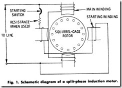
The split-phase induction motor is one of the most popular of the fractional-horsepower types. As shown in Fig. 1, the motor consists essentially of a squirrel-cage rotor and two stator windings (a main winding and a starting winding). The main winding is connected across the supply line in the usual manner, and has a low resistance and a high inductance. The starting or auxiliary winding, which is physically displaced in the stator from the main winding, has a high resistance and a low inductance. This physical displacement, in addition to the electrical phase displacement produced by the relative electrical resis tance values in the two windings, produces a weak rotating field which is sufficient to provide a low starting torque.
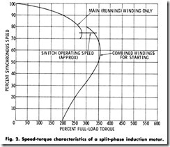
After the motor has accelerated to 75 or 80% of its synchronous speed, a starting switch (usually centrifugally operated) opens its contacts to disconnect the starting winding. The function of the starting switch (aft r the motor has started) is to prevent the motor from drawing excessive current from the line and to protect the starting winding from damage due to heating. The motor may be started in either direction by reversing the connections to either the main or auxiliary winding, but not to both. .
The characteristics of a resistance-type split-phase motor are shown in Fig. 2. The split-phase motor is most commonly used in sizes ranging from 1/30 hp (24.9W) to 1/2 hp (373 W) for applications such as fans, business machines, automatic musical instruments, buffing machines, etc.
Resistance-Start Motors
A resistance-start motor is a form of split-phase motor having a resistance connected in series with the auxiliary winding. The auxiliary circuit is opened by a starting switch when the motor has attained a predetermined speed.
Reactor- Start Motors
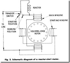
A reactor-start motor is a form of split-phase motor designed for starting with a reactor in series with the main winding. The reactor is short-circuited, or otherwise made ineffective, and the auxiliary (start ing) circuit is opened when the motor has attained a predetermined speed. A circuit arrangement for this type of motor is shown in Fig. 3. The function of the reactor is to reduce the starting current and to increase the angle of lag of the main- winding current behind the voltage. This motor will develop approximately the same torque as the split-phase motors discussed previously. The centrifugally-operated starting switch must be of the single-pole double-throw type for proper functioning.
CAPACITOR-START MOTORS
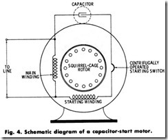
The capacitor-start motor is another form of split-phase motor having a capacitor connected in series with the auxiliary winding. The auxiliary circuit is opened when the motor has attained a predetermined speed. The circuit in Fig. 4 shows the winding arrangement.
The rotor is of the squirrel-cage type, as in other split-phase motors . The main winding is connected directly across the line, while the auxiliary or starting winding is connected through a capacitor which is connected into the circuit through a centrifugally-operated starting switch. The two windings are approximately 90% apart electrically.
This type of motor has certain advantages over the previously described types in that it has a considerably higher starting torque accompanied by a high power factor.
PERMANENT-CAPACITOR MOTORS
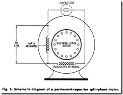
A permanent-capacitor type of motor has its main winding connected directly to the power supply, and the auxiliary winding connected in series with a capacitor. Both the capacitor and auxiliary winding remain in the circuit while the motor is in operation. There are several types of permanent-capacitor motors, differing from one another mainly in the number and arrangement of capacitors employed. The running charac teristics of this type of motor are extremely favorable, and the torque is fixed by the amount of additional capacitance, if any, added to the auxiliary winding during starting.
The simplest of this type of motor is the low-torque, permanent capacitor motor shown in Fig. 5. Here, a capacitor is permanently connected in series with the auxiliary winding. This type of motor can be arranged for an adjustable speed by the use of a tapped winding or an autotransformer regulator.
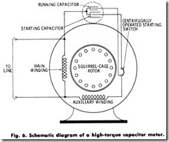
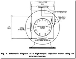
High-torque motors are usually provided with one running and one starting capacitor connected as shown in Fig. 6, or with an autotrans former connected to increase the voltage across the capacitor during the starting period, as indicated in Fig. 7.
REPULSION MOTORS
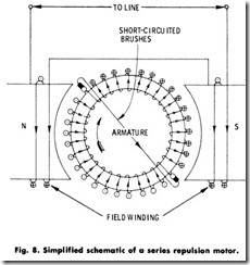
Repulsion motors have a stator winding arranged for connection to the source of power, and a rotor winding connected to a commutator. As shown in Fig. 8, brushes on the commutator are short-circuited and are so placed that the magnetic axis of the rotor winding is inclined to the magnetic axis of the stator winding. This type of motor has a varying speed characteristic.
Principally, it has a stator like that of a single-phase motor, but has a rotor like the armature of a de motor, with the opposite brushes on the annature short-circuited-that is, connected together by a connector with a negligible resistance.
The brushes are placed so that a line connecting them makes a small angle with the neutral axis of the magnetic field of the stator. The stator induces a current in the armature; the current produces an armature field with poles in the neighborhood of the brushes. These armature fields have the same polarity as the adjacent field poles, and are repelled by them so that this repulsion causes the armature to revolve. The motor derives its name from this action.
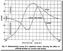
A repulsion motor of this original type has characteristics (Fig. 9) similar to those of the series motor. It has a high starting torque and moderate starting current. It has a low power factor, except at high speeds. For this reason, it is often modified into the compensated repulsion motor, which has another set of brushes placed midway between the short-circuited set and connected in series with the stator winding.
Repulsion-Start Induction Motors
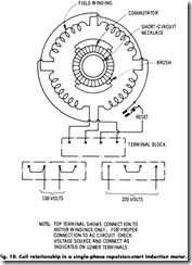
A repulsion-start induction motor is a single-phase motor having the same windings (Fig. 10) as a repulsion motor. At a predetermined speed, however, the rotor winding is short-circuited, or otherwise connected, to give the equivalent of a squirrel-cage winding. This type of motor starts as a repulsion motor, but runs as an induction motor with constant-speed characteristics .
The repulsion-start induction motor has a single-phase distributed field winding, with the axis of the brushes displaced from the axis of the field winding. The armature has an insulated winding. The current induced in the armature, or rotor, is carried by the brushes and commutator, resulting in a high starting torque. When nearly synchro nous speed is attained, the commutator is short-circuited, so that the armature is then similar in function to a squirrel-cage armature.
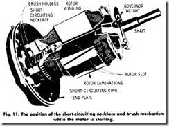
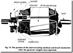
The photographs in Figs. 11 and 12 show the working principles of the mechanism for simultaneously lifting the brushes and short-circuit ing the commutator to change the operation from repulsion to induction. The object of lifting the brushes is to eliminate wear on the commutator during the running periods, since it makes no difference electrically whether the brushes are in contact or not after the motor comes up to speed.
This type of motor has gone through many stages of improvement since its first appearance on the market, although its general principle has remained the same. The general reliability of this type of motor is largely governed by the reliability of the short-circuiting mechanism. For this reason, it has been the constant aim of engineers to improve on the principle and construction of the short-circuiting switch.
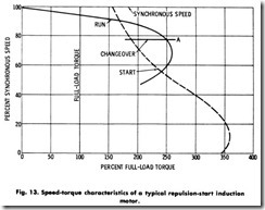
Since the motor starts on the repulsion principle, it has the same starting characteristics as the repulsion motor described previously namely, high starting torque and low starting current. As the motor speeds up, the torque falls off rapidly. At some point on the speed-torque curve, usually at about 80% of synchronism, the commu tator is automatically short-circuited, producing the effect of a cage winding in the armature, and the motor comes up to speed as an induction motor. After the commutator has been short-circuited, the brushes do not carry current and therefore may be lifted from the commutator, but lifting is not absolutely necessary.
The curve in Fig. 13 shows the speed-torque characteristics of a typical repulsion-start induction motor. The short-circuiting mechanism operates at point A, at which time the induction-motor torque is greater than the repulsion-motor torque. This means that if the repulsion winding has sufficient torque to bring the load up to this speed, there will be sufficient torque as an induction motor to bring the load up to full speed. The higher the speed at which the short-circuiting mechanism operates, the lower will be the induction-motor current at that point and, consequently, the less disturbance to the line. After the commutator has been short-circuited, the motor has the same characteristics as the single-phase induction motor previously described.
If the short-circuiting mechanism operates before the repulsion curve crosses the induction-motor curve, and if the torque of the induction motor is less than that required to accelerate the load, the motor may slow down until the short circuit is removed from the commutator, in which case the motor will again operate repulsion. The armature will then speed up until the commutator is again short-circuited, after which the armature will slow down until it again becomes repulsion. This cycle will be repeated over and over again until some change takes place.
The efficiency and the maximum running torque of the repulsion-start induction motor are usually less than those of a cage-wound induction motor of comparative size. In other words, a repulsion-start induction motor must be larger than a cage-wound motor of the same rating to give the same performance.
Repulsion-Induction Motors
A repulsion-induction motor is another form of repulsion motor which has a squirrel-cage winding in the rotor in addition to the repulsion winding. A motor of this type may have either a constant- speed or a varying-speed characteristic. Specifically, this motor is a combination of the repulsion and induction types and operates on the combined principle of both repulsion and induction. It is sometimes termed a squirrel-cage repulsion motor. In this motor, the desirable starting characteristics of the repulsion motor and the constant-speed characteristic of the induction motor are obtained. It is, of course, impossible to combine the two types of motors and obtain only the desirable characteristics of each.
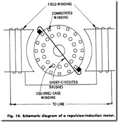
As shown in Fig. 14, the field has the same type of windings used in the repulsion -start induction motor, and the armature has two separate and independent windings. They are:
1. . Squirrel-cage winding ,
2. Commutated winding.
Both of these armature windings function during the entire period of operation of the motor. There are no automatic devices, such as the starting switch of the split-phase motor or the short-circuiting device of the repulsion-start induction motor.
The cage winding is located in slots below those which contain the commutated winding. The slots which contain the two windings may or may not be connected by a narrow slot. Usually, there are the same number of slots for the two windings. It is not, however, absolutely essential that they be the same. Because of its construction, the squirrel-cage winding inherently has a high inductance. Its reactance, with the armature at rest, is therefore high.
The commutated winding has a low reactance, with the result that most of the current will flow in this winding. The ideal condition at starting would be for all of the flux to pass beneath the commutated winding and none of it beneath the cage winding. If this condition could be obtained, this motor would have the same starting characteristics as the repulsion -start induction motor. However, at full-load speed, which is slightly below synchronism, the reactance of the cage winding is low, and most of the mutual flux passes beneath the cage winding. Both windings produce torque, and the output of the motor is the combined output of the cage winding and the commutated winding.
The commutation of the motor is good at all speeds. The no-load speed is above synchronism and is limited by the combined effect of the field winding on the commutated winding and the cage winding, and by the action of the two armature windings on each other. At synchronous speed, a squirrel-cage motor has no torque. At synchronous speed, and for a short distance above synchronous speed, the torque of a repul sion-induction motor is greater than that of the commutated winding alone. This shows that because of the interaction between the two armature windings, the squirrel cage supplies torque instead of acting as a brake.
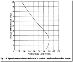
At full-load speed, and up to about the maximum running torque point, the torque of this motor is greater than the sum of the torques of the cage winding and the commutated winding. The inherent locked torque curve of a repulsion-induction motor, shown in Fig. 15, is similar to that of the repulsion motor. At soft neutral, the primary winding carries the squirrel-cage current in addition to the exciting current of the motor.
Since its starting current is low, the repulsion-induction motor may be operated from lighting circuits when driving frequently started devices. The repulsion-induction motor is especially suitable for such applications as household refrigerators, water systems, garage air pumps, gasoline pumps, compressors, etc.
