PRINCIPLE OF MOTOR OPERATION
The principle on which stepping motors are based is very simple. When a bar of iron or steel is suspended so that it is free to rotate in a magnetic Weld, it will align itself with the Weld. If the direction of the Weld is changed, the bar will turn until it is again aligned, by the action of the so-called reluctance torque. (The mechanism is similar to that of a compass needle, except that if a compass had an iron needle instead of a permanent magnet it would settle along the earth’s magnetic Weld but it might be rather slow and there would be ambiguity between N and S!)
Before exploring constructional details, it is worth saying a little more about reluctance torque, and its relationship with the torque-producing mechanism we have encountered so far in this book. The alert reader will be aware that, until this chapter, there has been no mention of reluctance torque, and might therefore wonder if it is entirely diVerent from what we have considered so far.
The answer is that in the vast majority of electrical machines, from generators in power stations down to induction and d.c. motors, torque is produced by the interaction of a magnetic Weld (produced by the stator windings) with current-carrying conductors on the rotor. We based our understanding of how d.c. and induction motors produce torque on the simple formula F ¼ BIl for the force on a conductor of length l carrying a current I perpendicular to a magnetic Xux density B (see Chapter 1). There was no mention of reluctance torque because (with very few exceptions) machines which exploit the ‘BIl’ mechanism do not have reluctance torque.
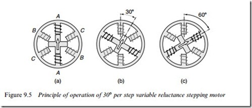
As mentioned above, reluctance torque originates in the tendency of an iron bar to align itself with magnetic Weld: if the bar is displaced from its alignment position it experiences a restoring torque. The rotors of machines that produce torque by reluctance action are therefore designed so that the rotor iron has projections or ‘poles’ (see Figure 9.5) that align with the magnetic Weld produced by the stator windings. All the torque is then produced by reluctance action, because with no conductors on the rotor to carry current, there is obviously no ‘BIl’ torque. In contrast, the iron in the rotors of d.c. and induction motors is (ideally) cylindrical, in which case there is no ‘preferred’ orientation of the rotor iron, i.e. no reluctance torque.
Because the two torque-producing mechanisms appear to be radically diVerent, the approaches taken to develop theoretical models have also diverged. As we have seen, simple equivalent circuits are available to allow us to understand and predict the behaviour of mainstream ‘BIl’ machines such as d.c. and induction motors, and this is fortunate because of the overwhelming importance of these machines. Unfortunately, no such simple treatments are available for stepping and other reluctance-based machines. Circuit-based numerical models for per- formance prediction are widely used by manufacturers but they are not really of much use for illuminating behaviour, so we will content ourselves with building up a picture of behaviour from a study of typical operating characteristics.
The two most important types of stepping motor are the variable reluctance (VR) type and the hybrid type. Both types utilise the reluctance principle, the diVerence between them lying in the method by which the magnetic Welds are produced. In the VR type the Welds are produced solely by sets of stationary current-carrying windings. The hybrid type also has sets of windings, but the addition of a permanent magnet (on the rotor) gives rise to the description ‘hybrid’ for this type of motor. Although both types of motor work on the same basic principle, it turns out in practice that the VR type is attractive for the larger step angles (e.g. 158, 308, 458), while the hybrid tends to be best suited when small angles (e.g. 1.88, 2.58) are required.
Variable reluctance motor
A simpliWed diagram of a 308 per step VR stepping motor is shown in Figure 9.5. The stator is made from a stack of steel laminations, and has six equally spaced projecting poles, or teeth, each carrying a separate coil. The rotor, which may be solid or laminated, has four projecting teeth, of the same width as the stator teeth. There is a very small air-gap – typically between 0.02 and 0.2 mm – between rotor and stator teeth. When no current is Xowing in any of the stator coils, the rotor will therefore be completely free to rotate.
Diametrically opposite pairs of stator coils are connected in series, such that when one of them acts as a N pole, the other acts as a S pole. There are thus three independent stator circuits, or phases, and each one can be supplied with direct current from the drive circuit (not shown in
Figure 9.5). When phase A is energised (as indicated by the thick lines in Figure 9.5(a)), a magnetic Weld with its axis along the stator poles of phase A is created. The rotor is therefore attracted into a position where the pair of rotor poles distinguished by the marker arrow line up with the Weld, i.e. in line with the phase A pole, as shown in Figure 9.5(a). When phase A is switched-oV, and phase B is switched-on instead, the second pair of rotor poles will be pulled into alignment with the stator poles of phase B, the rotor moving through 308 clockwise to its new step position, as shown in Figure 9.5(b). A further clockwise step of 308 will occur when phase B is switched-oV and phase C is switched-on. At this stage the original pair of rotor poles come into play again, but this time they are attracted to stator poles C, as shown in Figure 9.5(c). By repetitively switching on the stator phases in the sequence ABCA, etc. the rotor will rotate clockwise in 308 steps, while if the sequence is ACBA, etc. it will rotate anticlockwise. This mode of operation is known as ‘one-phase-on’, and is the simplest way of making the motor step. Note that the polarity of the energising current is not signiWcant: the motor will be aligned equally well regardless of the direction of current.
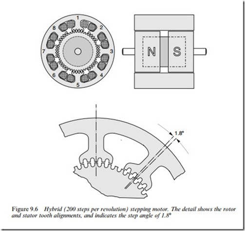
An alternative form of VR motor is the multi-stack type, consisting of several (typically three) magnetically independent sections or ‘stacks’ within a single housing. In a three-stack motor the rotor will consist of three separate toothed sections on a common shaft, each having the same number of equispaced teeth, but with the teeth on each section displaced by one-third of a tooth pitch from its neighbour. The stator also has three separate stacks each of which looks rather like the stator of a hybrid motor (see Figure 9.6), with the teeth on each stator pole having the same pitch as the rotor teeth. The three stator stacks have their teeth aligned, and each stator has a winding, which excites all of its poles.
For one-phase-on operation each stator is energised sequentially, so that its respective rotor teeth are pulled into alignment with the stator teeth. Stepping occurs because successive sets of rotor teeth are mis- aligned by one step. The principal diVerence as compared with the single-stack VR motor (see Figure 9.5) is that all the rotor teeth on any one stack contribute to torque when that particular stack is ener- gised. The overall utilisation of materials is no better than the single- stack type, however, because only one-third of the material is energised at a time.
Hybrid motor
A cross-sectional view of a typical 1.88 hybrid motor is shown in Figure
teeth, and separated by a permanent magnet. The rotor teeth have the same pitch as the teeth on the stator poles, and are oVset so that the centreline of a tooth at one end-cap coincides with a slot at the other end-cap. The permanent magnet is axially magnetised, so that one set of rotor teeth is given a N polarity, and the other a S polarity.
When no current is Xowing in the windings, the only source of magnetic Xux across the air-gap is the permanent magnet. The magnetic Xux crosses the air-gap from the N end-cap into the stator poles, Xows axially along the body of the stator, and returns to the magnet by crossing the air-gap to the S end-cap. If there were no oVset between the two sets of rotor teeth, there would be a strong periodic alignment torque when the rotor was turned, and every time a set of stator teeth was in line with the rotor teeth we would obtain a stable equilibrium position. However, there is an oVset, and this causes the alignment torque due to the magnet to be almost eliminated. In practice a small ‘detent’ torque remains, and this can be felt if the shaft is turned when the motor is de-energised: the motor tends to be held in its step positions by the detent torque. This is sometimes very useful: for example, it is usually enough to hold the rotor stationary when the power is switched- oV, so the motor can be left overnight without fear of it being acciden- tally nudged into to a new position.
The eight coils are connected to form two phase-windings. The coils on poles 1, 3, 5 and 7 form phase A, while those on 2, 4, 6 and 8 form phase B. When phase A carries positive current stator poles 1 and 5 are magnetised as S, and poles 3 and 7 become N. The oVset teeth on the N end of the rotor are attracted to poles 1 and 5 while the oVset teeth at the S end of the rotor are attracted into line with the teeth on poles 3 and 7. To make the rotor step, phase A is switched-oV, and phase B is energised with either positive current or negative current, depending on the sense of rotation required. This will cause the rotor to move by one-quarter of a tooth pitch (1.88) to a new equilibrium (step) position.
The motor is continuously stepped by energising the phases in the sequence þA, – B, – A, þ B, þ A (clockwise) or þA, þ B, – A, – B, þA (anticlockwise). It will be clear from this that a bipolar supply is needed (i.e. one which can furnish þve or -ve current). When the motor is operated in this way it is referred to as ‘two-phase, with bipolar supply’.
If a bipolar supply is not available, the same pattern of pole energisa- tion may be achieved in a diVerent way, as long as the motor windings consist of two identical (‘biWlar wound’) coils. To magnetise pole 1 north, a positive current is fed into one set of phase A coils. But to magnetise pole 1 south, the same positive current is fed into the other set of phase A coils, which have the opposite winding sense. In total, there are then four separate windings, and when the motor is operated in this way it is referred to as ‘4-phase, with unipolar supply’. Since each winding only occupies half of the space, the MMF of each winding is only half of that of the full coil, so the thermally rated output is clearly reduced as compared with bipolar operation (for which the whole winding is used).
We round oV this section on hybrid motors with a comment on identifying windings, and a warning. If the motor details are not known, it is usually possible to identify biWlar windings by measuring the resistance from the common to the two ends. If the motor is intended for unipolar drive only, one end of each winding may be commoned inside the casing; for example, a 4-phase unipolar motor may have only Wve leads, one for each phase and one common. Wires are also usually colour-coded to indicate the location of the windings; for example, a biWlar winding on one set of poles will have one end red, the other end red and white and the common white. Finally, it is not advisable to remove the rotor of a hybrid motor because they are magnetised in situ: removal typically causes a 5–10% reduction in magnet Xux, with a corresponding reduction in static torque at rated current.
Summary
The construction of stepping motors is simple, the only moving part being the rotor, which has no windings, commutator or brushes: they are therefore robust and reliable. The rotor is held at its step position solely by the action of the magnetic Xux between stator and rotor. The step angle is a property of the tooth geometry and the arrangement of the stator windings, and accurate punching and assembly of the stator and rotor laminations is therefore necessary to ensure that adjacent step positions are exactly equally spaced. Any errors due to inaccurate punching will be non-cumulative, however.
The step angle is obtained from the expression
The VR motor in Figure 9.5 has four rotor teeth, three stator phase windings and the step angle is therefore 308, as already shown. It should also be clear from the equation why small angle motors always have to have a large number of rotor teeth. Probably the most widely used motor is the 200 steps per revolution hybrid type (see Figure 9.6). This has a 50 tooth rotor, 4-phase stator, and hence a step angle of 1.88 ( ¼ 360o=(50 x 4)).
The magnitude of the aligning torque clearly depends on the magnitude of the current in the phase winding. However, the equilibrium positions itself does not depend on the magnitude of the current, because it is simply the position where the rotor and stator teeth are in line. This property underlines the digital nature of the stepping motor.


