Pressure Sensor with Altitude Correction
In newer gasoline injection systems, the pres sure sensor contains two aneroids, but only one of these is evacuated-the other is open to the atmo sphere. By this arrangement not only the absolute pressure in the intake manifold is taken into ac count, but also the difference between the atmo spheric pressure and the pressure in the manifold. Practically speaking, this means that in the part load range the engine is matched far better to changes in altitude, Fig. 30.
Temperature Sensor (Intake Air}
The injected fuel quantity is controlled pri marily by the absolute pressure in the intake mani fold, with a correction made for the engine speed. However, this control of the injected fuel quan tity is only exact at constant temperature, because at low ambient temperatures the weight of the air drawn in is greater, so the air-fuel mixture be comes leaner if the control system does not take the air temperature into account. This becomes of greatest importance at ambient temperatures of -20° C. to 0° C. ( -4° F. to 32° F.) when Combustion Miss can result. In order to avoid this disadvantage, a temperature sensor is installed in the intake manifold. This sensor reacts to decreas ing air temperatures by increasing the injected fuel quantity corresponding to the increase in the air density, Fig. 31.
The temperature sensor consists of a metal body shaped like a hexagonal-head screw inside which a so-called NTC resistor is installed. NTC stands for “Negative Temperature Coefficient” and means that the resistance of this type of resistor decreases sharply as its temperature increases.
Control System
The purpose of the control system in the ECGI is to meter a precise volume of fuel, corresponding to engine operating conditions, and to ensure its delivery to the charge of air drawn in by the en gine during each operating cycle.
Electronic Control Unit (ECU}
The most important unit in the ECGI system is the Electronic Control Unit ( ECU) which is re sponsible for metering the fuel quantity. The items of information needed for this are collected by transducers (pressure sensors, temperature sen sors, etc.) and are fed as electrical quantities to the ECU. After processing these quantities, the ECU generates the current pulses (opening pulses) which excite the solenoid coil of the sole noid-operated injection valves.
Depending on its design, the ECU is construct ed of 250-300 components, including about 30 transistors and 40 diodes. The unit operates at battery voltage but voltage variations occurring during driving do ·not affect its functioning. The electrical units of the injection system are con nected to the ECU through a cable harness wl;lich is terminated in a 25-pole plug. When the ignition is turned on, the injection system is made opera tional through a relay.
The ECU is designed on the basis of printed circuit engineering. We already foresee, however, that as a result of the introduction of integrated circuits in the unit, its consb:uction costs can be reduced and its reliability increased still further.
Correction Factors
In addition to the exact metering of fuel for full- or part-load under normal (warm) operating conditions of the engine, the following series of additional correction factors are required for per fect engine performance:
1. Enrichment of the mixture for cold starting.
2. Matching of the mixture during engine warm up.
3. Enrichment of the mixture when accelerat ing.
4. Cut-off of fuel during engine braking (now superseded in some cases by combustion during this mode of operation).
Cold Starting
When the engine is cold some fuel condenses in the intake manifold and on the cylinder walls.
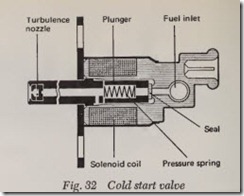
As a result, less fuel is mixed with the air drawn in to form a combustible mixture than in a warm engine; that is, a homogenous, combustible mix ture is not formed. If the mixture is too lean, ignition combustion miss can take place. The func tion of the solenoid-operated cold-start valve, Fig. 32, near the air throttle valve is to enrich the air in the intake manifold with finely atomized fuel. It injects fuel only when the starting motor is ac tivated and when at the same time a thermoswitch or thermo time switch immersed in the coolant (or fitted in the engine compartment) is closed.
Depending on the temperature it senses, the thermoswitch intenupts or completes the electric circuit leading to the cold-start valve. The thermo time switch performs the same function as the thermoswitch, but also limits the time that the valve is switched on.
Solenoid-Operated Cold-Start Valve
Great importance is placed on fine atomization of the fuel in the solenoid-operated cold-start valve, Fig. 32. A helical spring presses the movable plunger of the magnetic circuit with its seal against the valve seat and blocks the incoming How of fuel. When the plunger is drawn back the valve seat is freed. The fuel then flows laterally past the plunger and reaches the turbulence noz zle. In this nozzle the fuel is given a rotating movement and is discharged from the nozzle in a finely atomized condition.
Warm-Up
The warm-up phase of engine operation follows the cold start. During this phase the engine re quires considerable fuel enrichment because a portion of the fuel condenses on the cold cylinder walls. Moreover, without additional fuel emich ment a considerable drop in engine speed would be noticeable after fuel injected from the cold-start valve is cut off.
As the temperature increases, the enrichment steadily decreases, and it stops when the operating temperature is reached. This process is controlled in water-cooled engines by a temperature sensor immersed in the coolant and in air-cooled engines by a sensor in the cylinder head. Enrichment also takes place during starting operations, so that at low temperatures, additional fuel to that sprayed into the manifold by the cold-start valve is pro vided. Immediately after starting at -20° C. ( -4° F.), two to three times as much fuel must be injected, depending on engine type, than when the engine has reached operating temperature.
In addition to a richer air-fuel mixture during cold-start and the following warm-up phases of operation, a larger volume of air is also required during idling. In order to overcome the higher frictional losses the engine must produce a greater torque during idling. This is made possible by the so-called auxiliary charge of air. The auxiliary charge of air is controlled by a bypass valve, the auxiliary air valve, which bypasses the air throttle valve.
Auxiliary Air Valve
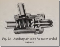
In the auxiliary air valve, Fig. 33, a temperature dependent expansion element moves a control pis ton and changes the flow area of the air duct. The area of the variable opening in the duct is changed dependent on the temperature so that at every starting temperature the desired idle speed can be attained. As the engine temperature increases, the area of the air duct is continually reduced and
at a coolant temperature of about +60° C. to +70° C. ( 141° F. to 159° F.) the duct is com pletely closed.
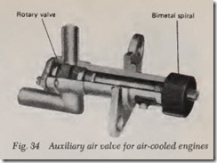
The auxiliary air valve can also be designed as a rotary valve, which is activated by a bimetal spiral. In air-cooled engines the bimetal spiral is inserted in the crankcase and surrounded by the engine oil vapors, Fig. 34.
Acceleration
When the air throttle valve is opened quickly, for example, during acceleration, the pressuresen sor reports the pressure rise with a slight delay to the ECU. This slight response delay is present because the pressure build-up in the intake mani fold (and thus in the pressure sensor ) requires a certain time after the change in position of the throttle plate. In order to bridge this slight delay in pressur e sensor response, the throttle position switch is fitted with auxiliary contacts which cause additional injection pulses to be generated by the ECU when the throttle valve is opening.
Throttle Position Switch
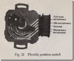
The sliding contacts in the throttle position switch slide over contact tracks and are actuated directly by the throttle plate shaft depending on the movement of the throttle plate. They bridge the contact tracks, thereby causing additional opening pulses to be generated by the ECU for acceleration enrichment, or fuel cut-off, when the vehicle is operating in an engine braking mode. In newer systems the throttle position switch, Fig. 35, performs the function of full-load enrichment.
Full-Load Operation
During part-load operation the fuel is metered so that the fuel consumption and the proportion of unburned components in the exhaust gas are kept as low as possible. When operating under f ull-load, however, the injected fuel quantity is determin ed on the basis of attaining maximum engine power; for example, additional fuel must be injected at such a time. Information required for this full-load enrichment is provided from the pressure switch, or the diaphragm section of the pressure sensor.
In newer systems the full-load enrichment is controlled by an additional contact in the throttle position switch. As a result, in these systems the pressure switch, or the diaphragm section of the pressure sensor, is not used for full-load enrich ment.
Engine Braking
When the engine is driven by the rolling vehicle ( for example, on a downgrade), the air throttle valve is fully closed. In order to save fuel and to reduce the exhaust emission, the fuel supply is completely cut off during this mode of operation. In order to keep the engine from stalling if. the clutch is disengaged, however, the supply of fuel is restored at engine speeds between 1,000 and 1,500 rpm. In the same way, injection is resumed if the engine speed approaches the idle speed when the vehicle is braked. The “air throttle valve closed” inform ation is signalled by the throttle position switch to the ECU, which calculates the engine speed on the basis of tl1e intervals between the triggering pulses received from the distributor.
In some other systems, combustion is continued during engine braking and the engine finds its own speed on the basis of this mode of operation. The reason combustion is continued in these sys tems is that fewer harmful exhaust components are emitted from an engine which is running, than from an engine in which the combustion chamber has cooled off following the cessation of combus tion. When the combustion chamber has cooled off, this results in poor mixing of the air and fuel whi ch, when combustion starts again, leads to the emission of an impermissible level of unburned, and therefore harmf ul, exhaust components.
![Fig. 30 Pressure sensor without enrichment_thumb[1] Fig. 30 Pressure sensor without enrichment_thumb[1]](http://machineryequipmentonline.com/electric-equipment/wp-content/uploads/2020/07/Fig.-30-Pressure-sensor-without-enrichment_thumb1_thumb.jpg)
![Fig. 31 Intake air temperature sensor location_thumb[1] Fig. 31 Intake air temperature sensor location_thumb[1]](http://machineryequipmentonline.com/electric-equipment/wp-content/uploads/2020/07/Fig.-31-Intake-air-temperature-sensor-location_thumb1_thumb.jpg)


