The Electric Windshield Wiper Circuit
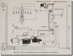
The circuit shown in Fig. 29 is used for a single motor which operates two wiper arms and provides a fixed parking position. It includes the battery, wiper motor, wiper switch, ammeter, con necting wires and car frame.
Through crank action the motor operates two wiper arms and blades whenever the control switch is turned on. Usually the control switch includes a resistor which is connected in the cir cuit to give a second speed to the wiper motor.
Some windshield wiper motors are designed to operate only one arm. These are usually con nected with a single wire from the motor through the switch and ammeter to the battery.
The Instrument Circuit
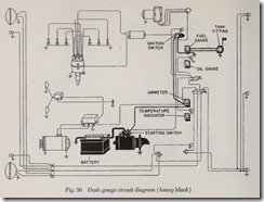
This eireuit, Fig. 30, includes the generator, generator tell-tale light, fuel gauge, temperature gauge, and oil pressure tell-tale light. In actual practice, the generator dash unit may be either a tell-tale light or ammeter, the oil pressure dash unit either a tell-tale light or a pressure gauge, and the engine temperature dash unit either a tell tale light or a temperature gauge. The gasoline supply dash unit is, of course, invariably a gauge rather than a warning light.
The arrangement in Fig. 30 with warning lights for generator and oil pressure and a gauge for temperature was chosen to show typical wiring for both type dash units. In rare cases, engine tem perature and oil pressure indicators are gauges that read the appropriate information directly and are connected to the engine independent of, and without connection to, the electrical system.
No matter whether a ‘gauge or a warning light is used, electrical oil pressure and temperature indi cators are similar in operation and circuitry to the fuel gauge. These circuits include the battery, an electrical sending unit mounted at the appropriate point on the engine or in the fuel tank and the dash mounted warning light or gauge. They are activated by the ignition switch so that when it is turned off the circuits are inoperative.
Electrical fuel, oil and temperature gauges may have one or two wires connecting the dash unit to the sending unit but all have a circuit which begins at the battery and is grounded in the sene unit.
The Lighting Circuit
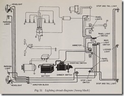
The lighting eireuit, Fig. 31, consists of the battery, generator tell-tale light, many lights, var ious switches, connecting wires and car frame.
The lights may be for road lighting, panel light ing, signaling or for some other purpose. Each light or set of lights has one or more switches to control its use.
Some installations may not have as many lights as illustrated in Fig. 31, while other applications may have more. However, any additional lamps usually have a simple circuit from the battery through the ammeter (or indicator light) to the control switch or switches where it divides and goes to each lamp. The lamp socket is grounded to complete the circuit.
Protective devices consisting of fuses, fusible links and thermal cutouts are used in various combinations in the lighting and other circuits to prevent damage to electrical units and the fire hazard of circuit overloading. Such devices func tion by interrupting the circuit when current flow exceeds a certain figure, such as occurs when a wire short circuits.
There are other electrical circuits designed to control automatic transmissions , overdrives, power tops and other devices. Such circuits are widely varied, apply only to one particular appli cation and do not have the univ ersal usage of those already described.
12 VOLT ELECTRICAL SYSTEMS
The 12 volt electrical system, adopted on most cars starting in 1953, was chosen over the old 6 volt system for several reasons:
1. To provide adequate power to feed the ever growing number of electrical accessories used on present day cars.
2. To provide greater starting torque with the same size starters.
3. To provide greater available voltage in the ignition system for higher speed, higher compression engines.
4. To permit smaller diameter wiring to be used in the electrical system.
Generator Requirements
In 1935 or thereabouts, passenger car gener ators were designed to produce about 20 amperes. In 1952, generator capacity was increased to over 50 amperes in some cases and even this hlgh output was found to be insufficient to supply the electrical needs of all the accessories used on some For all practical purposes, the limit of generator output was reached in 1952 with a 6-volt system as generators had become bulky and wiring heavy and clumsy. With a 12-volt system, the same amount of electrical power can be delivered with half the amperage, because power is measured in watts, which are simply amperes multiplied by volts. In other words, when a generator is re- quired to deliver 600 watts, this amount of power can be delivered in two ways: 100 amperes at 6 volts or 50 amperes at 12 volts. In each case the amperes multiplied by the volts produces the same number of watts ( 600).
As it is the current in amperes flowing through a conductor that determines the required size or gauge of the wire, it is obvious that with a 12-volt system, smaller size wires can be used to deliver the same amount of power as the larger sizes would deliver in a 6-volt system.
Ignition System Requirements
Turning to the ignition system, the adoption of high speed, high compression 8-cylinder engines by most of the automotive industry has made it more difficult to maintain adequate voltage in the ignition system for all engine operating conditions.
Compression in the combustion chamber of the gasoline engine bears the same relation to the firing of a spark plug as does resistance in an elec trical conductor to the passage of current through it. The higher the resistance of the conductor, the less current can flow through it. The higher the compression ratio, the weaker the spark. More current can be forced through a conductor of a certain resistance value by increasing the voltage across the conductor. By the same token, the strength of the spark can be increased by increas ing the voltage across the spark plug. This is one reason for increasing the system voltage from 6 to 12 volts.
Another factor is the higher speeds developed by the new type engines. With higher speeds, the old 6-volt ignition coil does not get sufficient time to become thoroughly saturated and therefore cannot produce enough energy to create a good spark. The 12-volt system is one way of putting more energy into the coil at high speeds without overloading and burning the breaker points at the lower speeds.
Comparing the available outputs of 6 and 12- volt coils at 3600 rpm engine speed, the 6-volt coil will produce 16,000 volts whereas the 12-volt coil will produce 19,000 volts. Thus, at high engine speeds the 12-volt coil produces adequate voltages for this type of operation where the 6-volt coil frequently fails.
Electrical System Changes
With a 12-volt system, many changes had to be made in the electrical units of the car. The bat tery, starter, generator, ignition coil, the various electrical motors, the light bulbs-all had to be redesigned for 12-volt use but their basic con struction remains the same as the 6-volt units. However, the ignition distributor, breaker points and condenser remain the same as in the 6-volt system.


