Image transducers
An image transducer is a device that will transform an optical image into electrical signals. The simplest image transducers are parallel types, in which a matrix of photodiodes supplies signals to a set of wires. Until recently, this type of transducer was used only for small-scale applications (such as optical character recognition) or coarse images, but modern developments in integration have led to renewed interest in their use. For the most part, however, image transducers are overwhelmingly of the serial output type in which the image is broken up into a set of repetitive signals. The method of breaking up the image is scanning, a technique invented more than a century ago by Nipkov, and in its original mechanical form employed by Baird in his ‘Televisor’ of 1928. Nowadays, scanning means the deflection of an electron beam over a set of charges that are proportional to the illumination of parts of an image. However, a serial-register action that gives a similar signal output is used in modern solid-state TV cameras and is also termed scanning. The basis of TV scanning is the analysis of the picture into lines and fields. Samples of the picture brightness are taken at a large number of points along a line at the top of the picture. Each sample provides the amplitude of a brightness signal, which is an analogue signal for each line of the picture. As the line is scanned, vertical deflection of the scanning is also applied so that the next line to be scanned is a short distance below the first.
Although the picture could be completely analysed in one set of scan lines that traced parallel lines from the top to the bottom of the picture, TV scanning follows a more complex pattern. The principle of interlace is used, meaning that in a set of 600 lines (for example), the odd numbered lines 1, 3, 5, 7, etc. would be scanned, ending half way along line 299 and then returning to half way along the top of line 2 to scan the even numbered lines. This was historically used as a method of reducing the bandwidth of the electronic form of the TV picture while retaining a vertical repetition rate of 50 per second in order to reduce flickering.
In this book we are not concerned with TV methods except inasmuch as they affect the operation of the transducers, and this outline of scanning has been intended to explain the construction and use of the vidicon and the CCD pick-up devices. Computer monitors do not use interlace, and operate at higher horizontal and vertical scan rates.
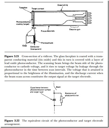
The vidicon principle is illustrated in Figure 3.21. The sensitive material is a photoconductor, now traditionally lead oxide (antimony trisulphide was formerly used). The photoconductor is laid onto a transparent conductive coating which extends through the glass seal to metal contacts on the outside of the tube – it is from this connection that the video output signals are taken. The tube is evacuated, and the electron gun can produce a finely focused beam that can be deflected in the usual line and field pattern. Where the beam strikes the photoconductor, the connection will make the potential at the photoconductor equal to the potential at the cathode of the electron gun.
A light image is projected so as to focus on to the faceplate of the vidicon. This will have the effect of lowering the resistance of the photoconductor where the image is bright, allowing this portion to charge to the potential of the transparent conducting layer. The photoconductor behaves like a combination of capacitor and resistor (Figure 3.22), so that between the times when the beam scans a point, the effect of the light is to build up an
amount of charge that is proportional to the brightness of the light at that point. When the scanning beam strikes this spot, it will be discharged, and the capacitive discharge current will flow in the transparent layer, forming the video signal. This signal is at a comparatively high level, so that the vidicon is well suited to producing good signals in comparatively low illumination. Colour signals are obtained by using three vidicons, with filters used to make the images consist of the primary light colours of red, green and blue.
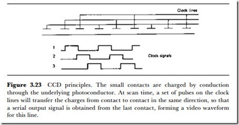
The solid-state image transducer is considerably more complex, and is made in IC form. The principle is to use the light intensity to charge a
capacitor and then to read the capacitor voltage by shifting it through a register. The digital type of shift register is unsuitable, and the device that is used is the CCD, charge-coupled device. This is a form of MOS device in which a clock pulse can pass a charge from one plate to another (Figure 3.23), like an analogue form of shift-register. The CCD type of TV camera pick-up device uses a large number of such devices that are arranged in lines. The lines are read out, giving a signal amplitude proportional to light brightness for each cell in the line, and a switching register ensures that the lines themselves are read in sequence. The picture quality does not approach that of the full-sized vidicon camera, but for very small cameras, or cameras that are used with low-resolution video-recorders (camcorders), the CCD type of device has the advantages of long life, high reliability, small size, and immunity to damage from bright lights.

