Radio waves
The range of electromagnetic waves in the frequency range from around 100 kHz to several thousand GHz are radio waves in the sense that we use transducers that are recognizably of the type that we have always associated with radio and radar, such as long wires, dipoles, yagis and dishes. Aerials are unusual among transducers in being reversible, so that an aerial can be used either for transmission or for reception, although its characteristics for one task may not be so favourable for the other task.
The purpose of the receiving aerial is to intercept some of the energy of the modulated wave radiated by the transmitting aerial. Wave theory indicates that this can be done most efficiently by an aerial whose length is any exact multiple of half wavelengths of the signal itself. The smallest effective length of an aerial is thus one half wavelength of the desired signal. Since the wavelength, in metres, of the signal is equal to
Although approximate, this is close enough for many purposes. A small error occurs because 3 x 10⁸ mjs is actually the velocity of electromagnetic waves in free space. The velocity in the metal conductors of the aerial is somewhat less. An aerial that uses a dipole of half-wavelength dimensions is a tuned aerial, and such tuning is essential if the aerial is to operate at high efficiency. We can often tolerate lesser efficiency figures, particularly for radio as distinct from TV applications, so that radio aerials in the past have used random lengths of wire (a long-wire aerial) or single (monopole) vertical rods as aerials. The older radio frequencies of the long-, medium- and short-wave bands would require long lengths of wire or rod for tuning, so that untuned aerials were a necessity, particularly for long wavelengths of several kilometres.
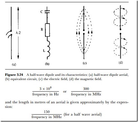
The most common tuned aerial element is the dipole shown in Figure 3.24(a), consisting of two equal-length rods connected to the transmitter or receiver via a feeder cable to the midpoint. The total length is approxi- mately a half wavelength. Consider first a dipole of this type connected to a transmitter. If the transmitter frequency matches the frequency to which the dipole is tuned, then the dipole behaves as if it were a resonant tuned circuit as shown in Figure 3.24(b) with an impedance that is completely
resistive. At frequencies on either side of this, the dipole acts either as an inductive or capacitive load to the transmitter, and a mismatch occurs, but there is a reasonable range of frequencies (bandwidth) for which the load is almost completely resistive. The resistance R of the equivalent circuit is usually called the radiation resistance for the aerial. R is not a physical resistance, only an equivalent one. If the aerial were replaced by a physical resistance of the same value, it would dissipate the same amount of heat energy as the aerial radiates electromagnetic energy into space.
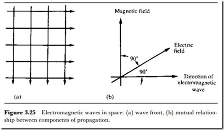
The AC voltage fed to the aerial causes each rod to take up opposite alternating polarities which give rise to the lines of force of electric field, shown in Figure 3.24(c). In a similar way, the AC current also produces alternating magnetic fields around the rods that generate the lines of force of electromagnetic field, shown in Figure 3.24(d). These forces act at right angles to each other and together cause the energy to be radiated away from the dipole. Figure 3.25(a) shows an electromagnetic wavefront approaching an observer, while Figure 3.25(b) depicts the mutual relationship between the two components of the electromagnetic radiation and the direction of the propagation of electromagnetic waves.
If a complementary receiving dipole is to collect the maximum signal from the radiated energy, then its conducting rods must cut the lines of the magnetic field at right angles. That is, the receiving dipole must occupy the same plane as the electric field of the radiation. If the angle is less than 90o, the induced signal voltage will be reduced proportionally. For instance, if the relative angle is 45o, the signal is 0.707 of maximum (3 dB down). The direction of the electric field of the wavefront is referred to as the plane of polarization of the wave. As shown above, this occupies the same plane as the transmitting and receiving dipoles. At very high frequencies and ultra high frequencies, vertical, slant and horizontal polarizations are all in common use.
• The angle of polarization of the transmitted wave can be changed if the signal is reflected from a substantial object, such as a hill, a gas-holder, or a block of buildings; and in some difficult reception areas a small change in the polarization angle to which the receiving aerial is set can give a significantly better signal level. Similar polarization adjustments can also be used, in the right conditions, to provide an additional way of discriminating against unwanted signals.
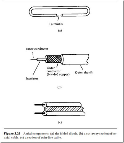
The radiation or feed-point resistance of the simple dipole is typically 75 Q. Up to a point, an increase in rod diameter will increase the bandwidth over which the aerial gives acceptable reception. The overall length of the dipole is normally cut for a frequency lying in the middle of the band of signals for which operation is wanted. Folding the dipole as shown in Figure 3.26(a) gives certain mechanical advantages but increases the radiation resistance to around 300 Q. This figure can be reduced to some extent by increasing the cross-sectional area of the conductors.
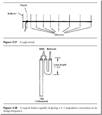
A single dipole on its own seldom gives satisfactory signal pick-up unless the receiver is situated very close to the transmitter. By adding to the aerial a reflector placed behind the dipole and a number of director rods placed in front of it, relative to the direction of the incoming signal, a much larger signal amplitude can be gathered. The aerial then becomes more highly directional (it has higher directivity), accepting only signals arriving from a limited angle in front of the array, i.e., from the direction in which the director rods lie. The addition of these extra elements lowers the aerials radiation resistance to nominally 75 Q.
An aerial consisting of a dipole, reflector and one or more directors
(Figure 3.27) is termed a yagi, and is the usual form of TV aerial for a fixed site. The design of a yagi array is quite complex. Not only does it have to have high directivity, a definite value of feed-point resistance and a high gain relative to a dipole, but these parameters have to be maintained over a sufficiently wide bandwidth. Not unexpectedly, aerials that are inadequately designed or which are made using poor materials often give very poor results. The factors that make all the difference are often not apparent to the eye (will the insulating material, for example, still be an insulator at 800 MHz on a wet day?). Aerials should always be bought from a reputable manufacturer who can specify and measure the aerials’ performance.
If transmissions are being beamed from a single fixed site, the yagi has to be properly mounted so that it is pointing directly at this transmitter. This can be done approximately using a compass bearing, or by using a field- strength meter connected to the aerial. A receiver itself cannot be used as a reliable guide to the received field strength unless its automatic gain
control (AGC) is disabled, because AGC action will itself serve to mask the effects of signal variations.
Where two differently sited transmitters can be received by a single aerial array, two yagis can be connected to the receiver through a diplexer (a signal combiner) obtainable from the aerial manufacturer. Where several transmitters can be received from different directions (as happens in many parts of the USA), a rotating aerial assembly is often the only solution.
The feeder cables are designed to carry the signal with the least possible
attenuation. Two common types of feeder are the twin-line of Figure 3.26(c), which is used extensively in the USA and has a 300 Q impedance, and the coaxial cable of Figure 3.26(b) which is used almost exclusively in the United Kingdom and parts of Europe, and has a 75 Q impedance. The impedances of aerial, feeder and receiver inputs must be correctly matched. An aerial system using 75 Q co-axial cable, for example, must be used to connect a 75 Q aerial and a 75 Q receiver input.
Twin-line feeders are described as being baLanced. With neither line earthed, the signals in the two lines are always anti-phase and of equal amplitude. On the other hand, co-axial cable is said to be unbaLanced, the earthed outer conductor acting as a shield for the signal-carrying inner conductor. A form of transformer called a baLun (balance to unbalance) is available (Figure 3.28) to match one cable system to the other.


