LEAKAGE FIELDS
Any magnetic field (Hi, Bi) zone within the IM is characterized by its stored magnetic energy (or coenergy) Wm.
![]()
![]() Wmi = 12 ∫∫∫V (B H dV⋅ ) = Li I2i2 (6.1)
Wmi = 12 ∫∫∫V (B H dV⋅ ) = Li I2i2 (6.1)
Equation (6.1) is valid when, in that region, the magnetic field is produced by a single current source, so an inductance “translates” the field effects into circuit elements.
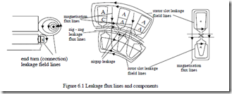
Besides the magnetic energy related to the magnetization field (investigated in Chapter 5), there are flux lines that encircle only the stator or only the rotor coils (Figure 6.1). They are characterized by some equivalent inductances called leakage inductances Lsl, Lrl.
There are leakage flux lines which cross the stator and, respectively, the rotor slots, end-turn flux lines, zig-zag flux lines, and airgap flux lines (Figure 6.1). In many cases, the differential leakage is included in the zig-zag leakage. Finally, the airgap flux space harmonics produce a stator emf as shown in Chapter 5, at power source frequency, so it should also be considered in the leakage category. Its torques occur at low speeds (high slips) and thus are not there at no–load operation.
. DIFFERENTIAL LEAKAGE INDUCTANCES
As both the stator and rotor currents may produce space flux density harmonics in the airgap (only step mmf harmonics are considered here), there will be both a stator and a rotor differential inductance. For the stator, it is sufficient to add all L1mν harmonics, but the fundamental (5.122), to get Lds.
The ratio σd of Lds to the magnetization inductance L1m is
![]() σdS0 = LL1dsm = ∑ν≠1 νK2Kwsws1ν22 ⋅ KKssν (6.3)
σdS0 = LL1dsm = ∑ν≠1 νK2Kwsws1ν22 ⋅ KKssν (6.3)
where KWsν, KWs1 are the stator winding factors for the harmonic ν and for the fundamental, respectively.
Ks and Ksν are the saturation factors for the fundamental and for harmonics, respectively.
As the pole pitch of the harmonics is τ/ν, their fields do not reach the back cores and thus their saturation factor Ksν is smaller then Ks. The higher ν, the closer Ksν is to unity. In a first approximation,
Ksν ≈ Kst < Ks (6.4)
That is, the harmonics field is retained within the slot zones so the teeth saturation factor Kst may be used (Ks and Kst have been calculated in Chapter 5). A similar formula for the differential leakage factor can be defined for the rotor winding.
![]() σdr0 = µ≠∑1 µ2Kwrwr1µ 2 ⋅ KKssµ
σdr0 = µ≠∑1 µ2Kwrwr1µ 2 ⋅ KKssµ
As for the stator, the order µ of rotor harmonics is (6.5)
µ = K m2 2 ±1 (6.6)
m2–number of rotor phases; for a cage rotor m2 = Z2/p1, also Kwr1 = Kwrµ = 1. The infinite sums in (6.3) and (6.5) are not easy to handle. To avoid this, the airgap magnetic energy for these harmonics fields can be calculated. Using (6.1)
µ0Fmν (6.7) Bgν= gK Kc sν
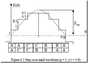
We consider the step-wise distribution of mmf for maximum phase A current, (Figure 6.2), and thus
2π Ns
![]() σds0 = ∫0 F2 ( )θ πdθ 1 ∑1 Fj2 ( )θ (6.8)
σds0 = ∫0 F2 ( )θ πdθ 1 ∑1 Fj2 ( )θ (6.8)
=
2
F1m 2 Ns F1m2
The final result for the case in Figure 6.2 is σdso = 0.0285.
This method may be used for any kind of winding once we know the number of turns per coil and its current in every slot. For full-pitch coil three-phase windings [1],
![]() σds ≈ 512q2q+2 1⋅ m K122 π2w12 −1 (6.9)
σds ≈ 512q2q+2 1⋅ m K122 π2w12 −1 (6.9)
Also, for standard two-layer windings with chorded coils with chording length ε, σds is [1]
ε = τ − y = (1− y/ τ)3q
![]() σds = m K22 π2 2 ⋅ 5q2 + −1 4 τ12q2 1− yτ 2 +1 −1 (6.10) 3 1− y 9q2
σds = m K22 π2 2 ⋅ 5q2 + −1 4 τ12q2 1− yτ 2 +1 −1 (6.10) 3 1− y 9q2
1 w1
In a similar way, for the cage rotor with skewed slots,
sinαer ⋅ τ
![]() with K’skew cc sin(αer /2); αer = 2π Np1r (6.12)
with K’skew cc sin(αer /2); αer = 2π Np1r (6.12)
= r ; ηr1 = αer /2 αer ⋅ τr
The above expressions are valid for three-phase windings. For a singlephase winding, there are two distinct situations. At standstill, the a.c. field produced by one phase is decomposed into two equal traveling waves. They both produce a differential inductance and, thus, the total differential leakage inductance (Lds1)s=1 = 2Lds.
On the other hand, at S = 0 (synchronism) basically the inverse (backward) field wave is almost zero and thus (Lds1)S=0 ≈ Lds.
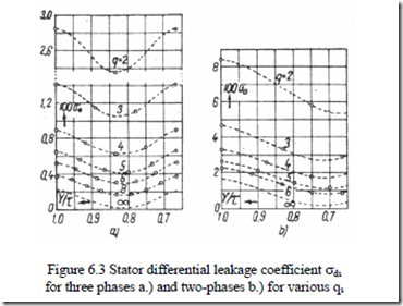
The values of differential leakage factor σds (for three- and two-phase machines) and σdr, as calculated from (6.9) and (6.10) are shown on Figures 6.3 and 6.4. [1]
A few remarks are in order.
• For q = 1, the differential leakage coefficient σds0 is about 10%, which means it is too large to be practical.
• The minimum value of σds0 is obtained for chorded coils with y/τ ≈ 0.8 for all qs (slots/pole/phase).
• For same q, the differential leakage coefficient for two-phase windings is larger than for three-phase windings.
• Increasing the number of rotor slots is beneficial as it reduces σdr0 (Figure 6.4).
Figures 6.3 do not contain the influence of magnetic saturation. In heavily saturated teeth IMs as evident in (6.3), Ks/Kst > 1, the value of σds increases further.
As the stator winding induced harmonic currents do not attenuate the rotor differential leakage: σdr = σdr0.
A rather complete study of various factors influencing the differential leakage may be found in [Reference 2].
Example 6.1. For the IM in Example 5.1, with q = 3, Ns = 36, 2p1 = 4, y/τ =
8/9, Kw1 = 0.965, Ks = 2.6, Kst = 1.8, Nr = 30, stack length Le = 0.12m, L1m = 0.1711H, W1 = 300 turns/phase, let us calculate the stator differential leakage inductance Lds including the saturation and the attenuation coefficient ∆d of rotor cage currents.
Solution
We will find first from Figure 6.3 (for q = 3, y/τ = 0.88) that σds0 = 1.16⋅10-2.
Also from Figure 6.5 for c = 1τs (skewing), Z2/p1 = 30/2 = 15, ∆d = 0.92. Accounting for both saturation and attenuation coefficient ∆d, the differential leakage stator coefficient Kds is
Kds = Kds0 ⋅ Ks ∆ =d 1.16 10⋅ −2 ⋅ 2.6 ⋅0.92 =1.5415 10⋅ −2 (6.14)
Kst 1.8
Now the differential leakage inductance Lds is
Lds = KdsL1m =1.5415 10⋅ −2 ⋅0.1711= 0.2637 10⋅ −3 H (6.15)
As seen from (6.13), due to the rather large q, the value of Kds is rather small, but, as the number of rotor slots/pole pair is small, the attenuation factor ∆d is large.
Values of q = 1,2 lead to large differential leakage inductances. The rotor cage differential leakage inductance (as reduced to the stator) Ldr is
Ldr ![]() = σdr0 K L = 2.8⋅10−2 ⋅ 2.6 L = 4.04 10⋅ −2 L1m (6.16)
= σdr0 K L = 2.8⋅10−2 ⋅ 2.6 L = 4.04 10⋅ −2 L1m (6.16)
σdr0 is taken from Figure 6.4 for Z2/p1 = 15, c/τr = 1, : σdr0 = 2.8⋅10-2. It is now evident that the rotor (reduced to stator) differential leakage inductance is, for this case, notable and greater than that of the stator.
RECTANDULAR SLOT LEAKAGE INDUCTANCE/SINGLE LAYER
The slot leakage flux distribution depends notably on slot geometry and less on teeth and back core saturation. It also depends on the current density distribution in the slot which may become nonuniform due to eddy currents (skin effect) induced in the conductors in slot by their a.c. leakage flux. Let us consider the case of a rectangular stator slot where both saturation and skin effect are neglected (Figure 6.6).
Ampere’s law on the contours in Figure 6.6 yields
H x b( )
s = ns h⋅ ⋅i xs ; 0 ≤ x ≤ hs (6.17)
H x b( ) s = ns ⋅i ; hs ≤ x ≤ hs + h0s
The leakage inductance per slot, Lsls, is obtained from the magnetic energy formula per slot volume.
2 Wms = i22 ⋅ 12 hs +∫0hµ0s0H x 2 2 hs hos
Lsls = i2 ( ) dx⋅L be s = µ0n Ls e 3bs + bos (6.18)
The term in square parenthesis is called the geometrical specific slot permeance.
![]() λ =s
λ =s ![]() s + ≈ 0.5÷2.5; h = (1 3÷ )10−3m (6.19)
s + ≈ 0.5÷2.5; h = (1 3÷ )10−3m (6.19)
3bs bos
It depends solely on the aspect of the slot. In general, the ratio hs/bs < (5−6) to limit the slot leakage inductance to reasonable values.
The machine has Ns stator slots and Ns/m1 of them belong to one phase. So the slot leakage inductance per phase Lsl is
Lsl = Ns Lsls = 2p qm1 1 Lsls = 2µ0W L12 e λs (6.20) m1 m1 p q1
The wedge location has been replaced by a rectangular equivalent area on Figure 6.6. A more exact approach is also possible.
The ratio of slot leakage inductance Lsl to magnetizing inductance L1m is (same number of turns/phase),
Lsl = π2 (gK KKW1c )2s qτ λs (6.21)
L1m 3
Suppose we keep a constant stator bore diameter Di and increase two times the number of poles.
The pole pitch is thus reduced two times as τ = πD/2p1. If we keep the number of slots constant q will be reduced twice and, if the airgap and the winding factor are the same, the saturation stays low for the low number of poles. Consequently, Lsl/L1m increases two times (as λs is doubled for same slot height).
Increasing q (and the number of slots/pole) is bound to reduce the slot leakage inductance (6.20) to the extent that λs does not increase by the same ratio. Our case here refers to a single-layer winding and rectangular slot.
Two-layer windings with chorded coils may be investigated the same way.


