3.1. INTRODUCTION
Induction machines contain magnetic circuits traveled by a.c. and traveling magnetic fields and electric circuits flowed by alternative currents. The electric circuits are insulated from the magnetic circuits (cores). The insulation system comprises the conductor, slot and interphase insulation.
Magnetic, electrical, and insulation materials are characterized by their characteristics (B(H) curve, electrical resistivity, dielectric constant, and breakdown electric field (V/m)) and their losses.
At frequencies encountered in IMs (up to tens of kHz, when PWM inverter fed), the insulation losses are neglected. Soft magnetic materials are used in IM as the magnetic field is current produced. The flux density (B)/magnetic field (H) curve and cycle depend on the soft material composition and fabrication process. Their losses in W/kg depend on the B-H hysteresis cycle, frequency, electrical resistivity, and the a.c. (or) traveling field penetration into the soft magnetic material.
Silicon steel sheets are standard soft magnetic materials for IMs. Amorphous soft powder materials have been introduced recently with some potential for high frequency (high speed) IMs. The pure copper is the favorite material for the stator electric circuit (windings), while aluminum or brass is used for rotor squirrel cage windings.
Insulation materials are getting thinner and better and are ranked into a few classes: A (1050C), B (1300C), F (1550C), H (1800C).
3.2. SOFT MAGNETIC MATERIALS
In free space the flux density B and the magnetic field H are related by the permeability of free space µ0 = 4π10-7H/m (S.I.)
BWbm2 = µ0 mH⋅HmA (3.1)
Within a certain material a different magnetization process occurs.
B = µ⋅H; µ = µ µ0 R (3.2)
In (3.2) µ is termed as permeability and µR relative permeability (nondimensional).
Permeability is defined for homogenous (uniform quality) and isotropic (same properties in all directions) materials. In nonhomogeneous or (and)
nonisotropic materials, µ becomes a tensor. Most common materials are nonlinear: µ varies with B.
A material is classified according to the value of its relative permeability, µR, which is related to its atomic structure.
Most nonmagnetic materials are either paramagnetic-with µR slightly greater than 1.0, or diamagnetic with µR slightly less than 1.0. Superconductors are perfect diamagnetic materials. In such materials when B Æ 0, µRÆ 0. Magnetic properties are related to the existence of permanent magnetic dipoles within the matter.
There are quite a few classes of more magnetic materials (µR>> 1). Among, them we will deal here with soft ferromagnetic materials. Soft magnetic materials include alloys made of iron, nickel, cobalt and one rare earth element and/or soft steels with silicon.
There is also a class of magnetic materials made of powdered iron particles (or other magnetic material) suspended in an epoxy or plastic (nonferrous) matrix. These softpowder magnetic materials are formed by compression or injection, molding or other techniques.
There are a number of properties of interest in a soft magnetic material such as permeability versus B, saturation flux density, H(B), temperature variation of permeability, hysteresis characteristics, electric conductivity, Curie temperature, and loss coefficients.
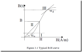
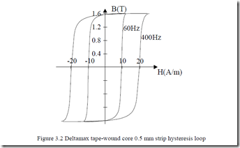
The graphical representation of nonlinear B(H) curve (besides the pertinent table) is of high interest (Figure 3.1). Also of high interest is the hysteresis loop (Figure 3.2).
There are quite a few standard laboratory methods to obtain these two characteristics. The B-H curve can be obtained two ways: the virgin (initial) BH curve, obtained from a totally demagnetized sample; the normal (average) BH curve, obtained as the tips of hysteresis loops of increasing magnitude. There is only a small difference between the two methods.
The B-H curve is the result of domain changes within the magnetic material. The domains of soft magnetic materials are 10-4-10-7m in size. When completely demagnetized, these domains have random magnetization with zero flux in all finite samples.
When an external magnetic field H is applied, the domains aligned to H tend to grow when increasing B (region I on Figure 3.1). In region II, H is further increased and the domain walls move rapidly until each crystal of the material becomes a single domain. In region III, the domains rotate towards alignment with H. This results in magnetic saturation Bs. Beyond this condition, the small increase in B is basically due to the increase in the space occupied by the material for B = µ0Hr0.
This “free space” flux density may be subtracted to obtain the intrinsic magnetization curve. The nonlinear character of B-H curve (Figure 3.1) leads to two different definitions of relative permeability.
|
• |
The normal permeability µRn: |
|
|
µRn = µB0H = tanµ0αn |
(3.3) |
|
|
• |
The differential relative permeability µRd: |
|
|
µRd = µdB = tanµαd |
(3.4) |
0dH 0
Only in region II, µRn = µRd. In region I and III, in general, µRn>µRd (Figure3.3). The permeability is maximum in region II. For M19 silicon steel sheets (Bs
= 2T, Hs = 40,000 A/m, µRmax= 10,000).
So the minimum relative permeability is 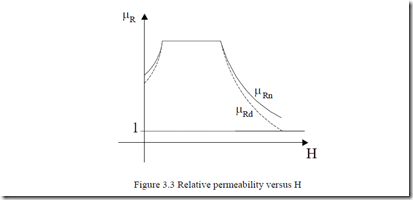
The second graphical characteristic of interest is the hysteresis loop (Figure3.2). This is a symmetrical hysteresis loop obtained after a number of reversals of magnetic field (force) between ±Hc. The area within the loop is related to the energy required to reverse the magnetic domain walls as H is reversed. This nonreversible energy is called hysteresis loss, and varies with temperature and frequency of H reversals in a given material (Figure 3.2). A typical magnetization curve B-H for silicon steel nonoriented grain is given in Table3.1.
Table 3.1. B-H curve for silicon (3.5%) steel (0.5mm thick) at 50Hz
|
B(T) |
0.05 |
0.1 |
0.15 |
0.2 |
0.25 |
0.3 |
0.35 |
0.4 |
0.45 |
0.5 |
|
H(A/m) |
22.8 |
35 |
45 |
49 |
57 |
65 |
70 |
76 |
83 |
90 |
|
B(T) |
0.55 |
0.6 |
0.65 |
0.7 |
0.75 |
0.8 |
0.85 |
0.9 |
0.95 |
1 |
|
H(A/m) |
98 |
106 |
115 |
124 |
135 |
148 |
162 |
177 |
198 |
220 |
|
B(T) |
1.05 |
1.1 |
1.15 |
1.2 |
1.25 |
1.3 |
1.35 |
1.4 |
1.45 |
1.5 |
|
H(A/m) |
237 |
273 |
310 |
356 |
417 |
482 |
585 |
760 |
1050 |
1340 |
|
B(T) |
1.55 |
1.6 |
1.65 |
1.7 |
1.75 |
1.8 |
1.85 |
1.9 |
1.95 |
2.0 |
|
H(A/m) |
1760 |
2460 |
3460 |
4800 |
6160 |
8270 |
11170 |
15220 |
22000 |
34000 |
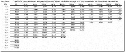
Table 3.2.
It has been shown experimentally that the magnetization curve varies with frequency as in Table 3.2. This time the magnetic field is kept in original data (Οe = 79.55A/m). [1]
In essence the magnetic field increases with frequency for same flux density B. Reduction of the design flux density is recommended when the frequency increases above 200 Hz as the core losses grow markedly with frequency.
3.3. CORE (MAGNETIC) LOSSES
Energy loss in the magnetic material itself is a very significant characteristic in the energy efficiency of IMs. This loss is termed core loss or magnetic loss. Traditionally, core loss has been divided into two components: hysteresis loss and eddy current loss. The hysteresis loss is equal to the product between the hysteresis loop area and the frequency of the magnetic field in sinusoidal systems.
Ph ≈ khfBm2[W/kg] ; Bm – maximum flux density (3.6)
Hysteresis losses are 10 to 30% higher in traveling fields than in a.c. fields for Bm< 1.5(1.6)T. However, in a traveling field they have a maximum, in general, between 1.5 to 1.6T and then decrease to low values for B > 2.0T. The computation of hysteresis losses is still an open issue due to the hysteresis cycle complex shape, its dependence on frequency and on the character of the magnetic field (traveling or a.c.) [2].
Preisach modelling of hysteresis cycle is very popular [3] but neural network models have proved much less computation time consuming. [4] Eddy current losses are caused by induced electric currents in the magnetic material by an external a.c. or traveling magnetic field.
Pe ≈ k f Be 2 m2[W / kg] (3.7)
Finite elements are used to determine the magnetic distribution-with zero electrical conductivity, and then the core losses may be calculated by some analytical approximations as (3.6)-(3.7) or [5]
σFe d f2 where K =1+
P ≈ k fB αK B( )+ 12 γFe 1/f 0.65Bdtm ∑n ∆Bi ex 1∫/f dBdt 1.5 dt (3.8) core h m m ∫ dB2 dt + K f
Bm -maximum flux density F -frequency
γFe -material density d -lamination thickness Kh -hysteresis loss constant
Kex -excess loss constant
∆BI -change of flux density during a time step
n -total number of time steps
Equation (3.8) is a generalization of Equations (3.6) and (3.7) for nonsinusoidal time varying magnetic fields as produced in PWM inverter IM drives.
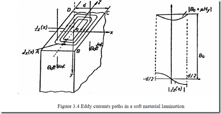
For sinusoidal systems, the eddy currents in a thin lamination may be calculated rather easily by assuming the external magnetic field H e0 jω1t acting parallel to the lamination plane (Figure 3.4).
Maxwell’s equations yield
 ∂∂Hxy = J ;z H0y = H e0 jω1t (3.9)
j H H ; y FeEz Jz
where J is current density and E is electric field.
As the lamination thickness is small in comparison with its length and width, Jx contribution is neglected. Consequently (3.9) is reduced to
![]() ∂∂2xH2y − ωj 1µσFeHy = ω σj 1 FeB0 (3.10)
∂∂2xH2y − ωj 1µσFeHy = ω σj 1 FeB0 (3.10)
B0 = µ0H0 is the initial flux density on the lamination surface. The solution of (3.10) is
Hy( )x = A e1 γx + A e2 −γx + Bµ00 (3.11)
![]() γ = β(1+ j ; B) = ω1µσFe (3.12)
γ = β(1+ j ; B) = ω1µσFe (3.12)
2
The current density Jz(x) is
.13)
|
The boundary conditions are |
||
|
Hyd2 = Hy−d2 = 0 Finally |
(3.14) |
|
|
A = A = B0 |
(3.15) |
1 2 2µcoshβ d (1+ j)
|
2 |
|
|
Jz ( )x = − β(1µ+ j) Bcosh0 sinhβ d(1(+1+j)βj)x 2 The eddy current loss per unit weight Pe is |
(3.16) |
Pe = d2σγFe 12 d / 2∫(Jz( )x )2dx = βγFeµdω1 B02 coshsinh((ββdd))−+sincos((ββdd))kgW (3.17)
Fe 0
The iron permeability has been considered constant within the lamination thickness although the flux density slightly decreases.
For good utilization of the material, the flux density reduction along lamination thickness has to be small. In other words βd << 1. In such conditions, the eddy-current losses increase with the lamination thickness.
The electrical conductivity σFe is also influential and silicon added to soft steel reduces σFe to (2-2.5)106 (Ωm)-1. This is why 0.5-0.6 mm thick laminations are used at 50(60) Hz and, in general, up to 200-300Hz IMs. For such laminations, eddy current losses may be approximated to
W ω σ2
Pe ≈ K Bw m2 kg; Kw = 1 24Fed2 γFe (3.18)
The above loss formula derivation process is valid for a.c. magnetic field excitation. For pure traveling field the eddy current losses are twice as much for same laminations, frequency, and peak flux density.
In view of the complexity of eddy current and hysteresis losses, it is recommended tests be run to measure them in conditions very similar to those encountered in the particular IM.
Soft magnetic material producers manufacture laminations for many purposes. They run their own tests and provide data on core losses for practical values of frequency and flux density.
Besides Epstein’s traditional method, made with rectangular lamination samples, the wound toroidal cores method has also been introduced [6] for a.c. field losses. For traveling field loss measurement, a rotational loss tester may be used. [7]
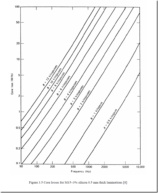
Typical core loss data for M15−3% silicon 0.5 mm thick lamination material−used in small IMs, is given in Figure 3.5. [8]
As expected, core losses increase with frequency and flux density. A similar situation occurs with a superior but still common material: steel M19 FP (0.4 mm) 29 gauge (Table 3.3). [1]
A rather complete up-to-date data source on soft magnetic materials characteristics and losses may be found in Reference 1.
Core loss represents 25 to 35% of all losses in low power 50(60) Hz IMs and slightly more in medium and large power IMs at 50(60) Hz. The development of high speed IMs, up to more than 45,000 rpm at 20 kW [9], has caused a new momentum in the research for better magnetic materials as core losses are even larger than winding losses in such applications.
Thinner (0.35 mm or less) laminations of special materials (3.25% silicon) with special thermal treatment are used to strike a better compromise between low 60 Hz and moderate 800/1000 Hz core losses (1.2 W/kg at 60 Hz, 1T; 28 W/kg at 800 Hz, 1T).
6.5% silicon nonoriented steel laminations for low power IMs at 60 Hz have been shown capable of a 40% reduction in core losses. [10] The noise level has also been reduced this way. [10] Similar improvements have been reported with 0.35mm thick oriented grain laminations by alternating laminations with perpendicular magnetization orientation or crossed magnetic structure (CMS). [11]
Soft magnetic composites (SFC) have been produced by powder metallurgy technologies. The magnetic powder particles are coated by insulation layers and a binder which are compressed to provide
• Large enough magnetic permeability
• Low enough core losses
• Densities above 7.1 g/cm3 (for high enough permeability)
The hysteresis loss tends to be constant with frequency while the eddy current loss increases almost linearly with frequency (up to 1 kHz or so).
At 400 to 500 Hz and above, the losses in SFC become smaller than for 0.5 mm thick silicon steels. However the relative permeability is still low: 100 to 200. Only for recent materials, fabricated by cold compression, the relative permeability has been increased above 500 for flux densities in the 1T range. [12, 13]
Added advantages such as more freedom in choosing the stator core geometry and the increase of slot-filling factor by coil in slot magnetic compression embedded windings [14] may lead to a wide use of soft magnetic composites in induction motors. The electric loading may be thus increased. The heat transmissivity also increases. [12]
In the near future, better silicon 0.5 mm (0.35 mm) thick steel laminations with nonoriented grain seem to remain the basic soft magnetic materials for IM fabrication. For high speed (frequency above 300 Hz) thinner laminations are to be used. The insulation coating layer of each lamination is getting thinner and thinner to retain a good stacking factor (above 85%).
![clip_image002[6] clip_image002[6]](http://machineryequipmentonline.com/electric-equipment/wp-content/uploads/2017/03/clip_image0026_thumb.jpg)