Ladder Diagrams
Ladder diagrams are used to present the electrical wiring in a control circuit. The diagram is made up of vertical lines that represent the control voltage and horizontal lines, or rungs, that represent the control circuits. The left line is the high-voltage or plus leg, and the right is the neutral or minus leg of the circuit. The control voltage can be AC or DC and can be any value needed but is usually from 0.5 to 220 V AC.
A rung is read from left to right. The inputs, contacts, or control devices are shown on the left. It is important to note that there are an unlimited number of input devices. Some are mechanical, others are electrical, and still others are solid-state. The one thing that you should understand is that whatever it is, it’s just a switch. It is either Open or Closed. There may be some external action that controls the input; e.g., a time-closed contact will close at a preset time after the timer is energized. But when it has completed its cycle, it is closed—no magic. The outputs are shown on the right of the rung. The exception—there is always an exception—is the motor controller overload contacts. They are always shown Normally Closed and are the last element(s) in the rung.
It is not possible and would be confusing to use pictures of the devices on the diagram. So standard symbols were developed. Symbols are the language of ladder diagrams; they depict the inputs and outputs of the circuit. The inputs are always shown in the off or no-voltage state unless otherwise noted on the diagram. However, they can be shown with mechanical devices such as springs holding them opened or closed. For example, a push button is shown in the neutral state, not pushed. A limit switch can be shown in a held Open or Closed state; its symbol will indicate this. The National Electrical Manufacturers Association (NEMA) Standards Publication ICS 19-2002 sets forth the standards for the use of symbols. A copy can be obtained at www.nema.org.
Not all engineers and manufacturers use standard symbols. So look for notes on the drawing for an explanation of unknown symbols. If you familiarize yourself with the electrical control symbols shown in detail in App. D and on this book’s website, you will be able to read most diagrams.
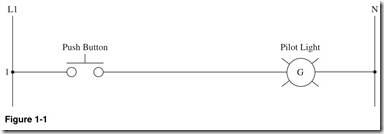
Figure 1-1 shows a simple ladder diagram. First we assume that there is voltage between the line L1 and the neutral N. From left to right the push button is Normally Open so the pilot light is off. When the push button is pressed, contact closes and the green pilot light turns on.
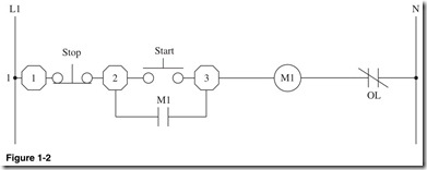
Figure 1-2 is the classic three-wire motor control circuit. It is called a three-wire circuit because the circuit has three wires that are external to the motor control box.
At the left of the circuit is the number 1. This is the line number. I like to use line numbers for the primary rungs so that it is easier to commu- nicate on the telephone or via e-mail. Next we have L1, which is the feed wire. Then we have an octagon symbol with the number 1 in it. This is the symbol I use for a terminal on a terminal strip. Different designers might use a rectangle, square, or circle. It will be obvious when you look at the dia- gram, and it should also be stated in the notes section of the diagram. The Normally Closed push button is used for the Stop button; when pressed, it opens the circuit. Next we have terminal 2. To the right is the Normally Open push button that is the Start button. When pressed, it completes the circuit and energizes the motor contactor coil M1. On the next line down is the Normally Open contact of motor contactor coil M1, as indicated by the M1 next to the contact. A coil or relay can have many contacts. They can be Normally Open or Closed; the symbol will indicate this. Then there is terminal 3 that connects to the Start button and the coil. The motor contac- tor coil M1 is the coil of the motor starter; when energized, it will close the contacts and start the motor. The last element in the rung is always the overload contact of the motor control starter. The circuit will be opened by the overload contact if the motor circuit rises above a preset current. Let’s recap. Push the Start button; it will close the circuit to the coil M1, and this will complete the circuit. This will close the contact M1, and the circuit will remain energized until the Stop button is pressed or the control power is lost. The electrically latched relay circuit will fail-safe so the motor will not come on when the power is restored.
Emergency Power Off (EPO) System Ladder Diagram
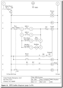
We will take a look at a more complex control circuit, using the diagram for an EPO system to illustrate the use of ladder diagrams and how to read them. NEC Section 645.10 requires that a computer room must have an EPO system to be classified as an IT Equipment Room under NEC 645. This system must disconnect all electrical power in the computer room. This is typically done by using shunt trip breakers on all the power circuit feeders. The system will have mushroom push buttons by each exit from the computer room. It may also be connected to a remote system or smoke detector panel to trigger the EPO system. Panel documentation
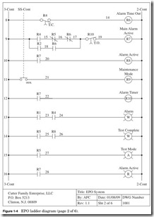
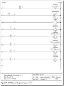
with this system comprises six pages. Pages 1, 2, and 3 are ladder diagrams (Figs. 1-3 to 1-5); page 4 is a contact layout and notes; page 5 is a bill of materials; and page 6 is the panel cover layout. For the complete package please see App. B.
There are three basic modes of operation:
Armed mode. System is energized, and the system is standing by for an alarm or reset.
Test mode. System is in the armed state, but the output contacts have been disconnected and will not close on alarm. This can be used to test the functions of the system without turning off the power or equipment.
Maint mode. System will not function, all controls will be in the neutral state, and the alarm will not function.
Shown in Fig. 1-6:
Line 1 On the left we have terminal 1, which is the hot leg, or L1, of the 120-V AC control circuit. On line 1 on the left is a key switch to turn the power on or off to the system.
The next element is the fuse. NEC 2008 Article 430-72 requires that there be overcurrent protection for the control circuit. The con- trol wiring is typically 14 gauge wire rated at 15 A (NEC 2008 Article
240.3 D-3) and is protected typically by a 10-A fuse.
The next element is the ground connection. The enclosure and the back plate of the panel must be grounded. Next we have terminal 2, which is the neutral leg, or L2, of the control circuit.
Line 2 The Power On indicator is a white pilot light that will be on whenever the system control power is on or energized.
Shown in Fig. 1-7:
Shown in Fig. 1-8:
Line 3 R1 is an 8-pole relay that can have any contact changed in the field from Normally Open to Normally Closed. See the bill of materials in Fig. 1-34. The relay will be on whenever the system control power is on or energized. This relay will be used in the circuit, but its primary use is to monitor the control voltage. One Normally Open contact is on line 6 and one is on line 24. One Normally Open contact is for external system monitoring of the AC power terminals 40 and 41. Four Normally Open contacts are for future-use terminals 42 to 49.
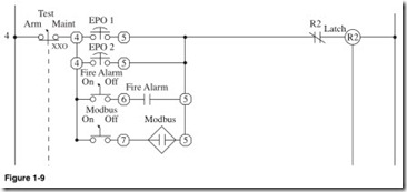
Shown in Fig. 1-9:
Line 4 The first element is the three-position key Selector switch. The three positions are arm, test, and maint. The XXO below the con- tact shows that the contact is closed in the arm and test positions. Next is terminal 4, then the first of the Normally Open Mushroom keyed release push buttons. Any number of contacts can be used to alarm the system; just put them in parallel with the current contacts.
The next line down is another Mushroom push button. NEC 645 requires that there be an alarm at each exit.
The next line down is the keyed Selector switch for the fire alarm interface contact. If there is a test of the fire alarm system, the panel can be set by the key switch to bypass the alarm. Next we have terminal 6. Then the next element is a contact from the fire alarm system that will close when the fire alarm is active.
The next element is terminal 5.
The next line down is the interface for the RS-485 module with Modbus communication. See the Modbus section of Chap. 4. The Modbus module interfaces the EPO system with a control center. If the keyed Selector switch is closed, the Modbus module will give the system monitoring personnel or software to alarm the panel if necessary. The next element we have is a Normally Open output from the Modbus.
The next element in line 4 is a Normally Closed contact from R2. This will open when relay R2 is latched. The next element is the R2 latching relay. The latching relay is mechanically held in place even if the power fails. The only way to reset the relay is to apply power to the unlatching coil. R2 has Normally Open contacts in lines 5, 6, and 17 and a Normally Closed contact in line 4.
Shown in Fig. 1-10:
Line 5 The first element is the Normally Open contact from the reset push button. When pushed after an alarm, the push button will reset and unlatch the R2 relay. The next element is a Normally Open contact from relay R8 on line 10. The next element is a Normally Open contact of R2, and it will be closed if the relay is latched.
In the next line down, the first element is a Normally Open contact of the Reset push button. Closing the push button will energize R3 which is the next element. R3 has a Normally Open contact on line 20.
