Resistance in-circuit test measurements
Critical resistance measurements of high-ohm resistors in a circuit are not too reliable.
Remove one end of the resistor and take another measurement (Fig. 2-16).
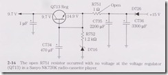
Fairly normal resistance measurements of low-ohm resistors and coils are quite close in resistance. Always remove one end of a diode in the circuit for correct resistance
measurements.
Resistance measurements with the diode test of the DMM across the transistor terminals are very accurate. When the same low resistance measurement is found between
any two transistor terminals, the transistor is leaky or shorted. Likewise, when all voltages on the base, collector, and emitter are quite close, suspect a leaky transistor.
Most failures in a transistor involve a short or a low ohm measurement between collector and emitter terminals.
When a low-ohm resistor or diode is found across a given component, the resistance measurement of the suspected part is not accurate.
For instance, a resistance measurement of a diode within a relay solenoid circuit is not normal because both components have a low resistance. Remove one end of the diode for a correct measurement.
Critical resistance measurements on the terminals of a transistor or IC to common ground might locate the leaky part. Resistance measurements in transistor and diode
tests with the DMM might determine if a suspected part is open or leaky.
Critical resistance measurements on the emitter or bias resistors might indicate a leaky transistor or IC or a change in resistance.
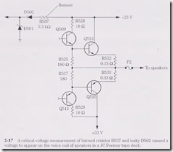
Within an audio amplifier, accurate resistance measurements on the speaker output terminals, with the speaker removed, can indicate a defective transistor or IC or a
change in resistance (Fig. 2-17).
Safe resistance measurements can be made with the power off when an output IC runs hot. Comparable resistance measurements in the stereo channels might help locate the defective part.
Of course, a resistance or continuity check of each component might turn up a defective part.
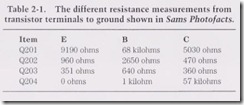
Very few schematics show the resistance measurements to ground, except Sams Photofacts (Table 2-1).
Continuity tests
A continuity or resistance check of a component is a quick way to determine if the part is open or leaky. Check the speaker terminals to see if the voice coil is open or grounded to the speaker magnet or framework. When taking speaker measurements with a DMM, the resistance should be quite close to the speaker impedance. With a VOM, the resistance might be off 1 or 2 ohms.
Continuity tests on the tape head can determine if the winding is open.
Place extra pressure on the tape head terminals if the winding is suspected of intermittent playback.
The continuity test between the tape head terminal and the outside shield might help clear up the problem of weak or distorted tape player sound.
Continuity checks of any component can determine if the part is open.
For instance, the resistance of a tape, VCR, or CD motor might not be known.
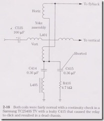
A quick continunity test across the deflection yoke windings can determine if the yoke is open (Fig.2-18).
However, a continuity test across the terminals can indicate if the motor winding is open or if there is a broken connection. Likewise, check switches, coils, and transformer connections with a continuity test
After installing a flyback transformer or IC component that solders directly to the PC board, continuity tests of the PC board wiring should be made. Check from the actual terminal pin to the next part tied to the same wiring to determine if the PC board wiring is intact. Sometimes the PC board wiring breaks at eyelets or terminal pins.
Bridge the wiring and resolder.
Leaky or shorted transistor resistance tests
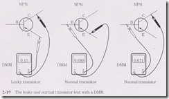
Resistance measurements across transistor terminals are not accurate with a VOM compared with a DMM. Within seconds you can check a suspected transistor be tween two elements with the DMM diode test. A low resistance measurement in both directions on any two terminals can indicate a shorted transistor or high leakage.
If a shorted output transistor has a 0.15-ohm measurement between the collector and emitter terminals on the DMM, the output transistor is shorted.
The transistor is leaky when the transistor has a 527-ohm reading in both directions.
If the measurement is in one direction with the red probe on the base terminal, the transistor is likely normal (Fig. 2-19).
Comparable resistance measurements of transistors to the common ground can indicate a defective circuit. Take comparable resistance measurements if transistors are damaged directly after replacement, especially in directly connected circuits. Take a resistance measurement between the output speaker terminal and the ground with the speaker removed in the amplifier’s
left and right channels. Compare the resistance readings in both channels to locate a possible defective circuit.
Usually only one channel is defective in a stereo amplifier. When the resistance measurements are not the same at a given point, take a resistance measurement from each terminal of the output transistors and compare these readings.
A normal circuit will have a similar resistance reading in both channels.
If the circuit is normal, the measurements of both channels will be within a few ohms of one another. Remember that this takes a lot of service time, and the DMM resistance reading must stop with each test.
When the measurements are still way off, go to the next transistor and compare this resistance measurement. If by chance the next stage is real close in measurement, just back up a step to the defective stage. Now is the time to take critical voltage and semiconductor tests.
IC resistance tests
Rotate the DMM to the 2-kilolim scale on the meter, and take a resistance measurements from each IC terminal to the common ground.
Double-check the resistance when a low reading is found. Some terminals of an IC may be connected directly to the common ground.
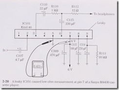
Simply check or trace it out. Now compare the same input and output terminals of a suspected IC in both channels. Usually only one channel is bad in a stereo
amplifier circuit. When the resistance reading is way off in one channel, suspect the IC with the lowest measurement (Fig. 2-20).
Sams Photofacts
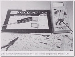
Most of the popular TV chassis with correct voltage measurements and waveforms are found in Sams Photofacts. Today, the Sams Technical Publishing Annual Index covers the TV chassis, TV/VCR combos, and VCR products. Besides a complete schematic, the service data might indicate grid trace location of parts, IC functions, important component information, adjustments, part lists, and a replacement chart. The replacement chart provides the latest semiconductor replacements for a given transistor, diode or IC (Fig. 2-21).
The schematics might include the audio, CRT, power supply, system control, TV, and tuner diagrams. There are also schematic notes, service tips, stereo adjustments, test equipment, test jig hookups, troubleshooting, and a tuner circuit voltage chart.
Sams Photofacts can be ordered from your local electronic distributor or directly from Sams:
Sams Technical Publishing
201 West 103d Street
Indianapolis, IN 46290-1097
1-800-428-SAMS
