The continuing rapid growth in the use of electricity for power and light ing is constantly spurred by a steady increase in the number and types of appliances, machines, and other devices powered by electric motors. In fact, the principal means of changing electrical energy into mechanical energy or power is the electric motor- ranging in size from small frac tional horsepower, low-voltage motors to the very large high-voltage syn chronous motors.
Electric motors are classified according to the following: size (horse power); type of application; electrical characteristics; speed, starting, speed control, and torque characteristics; and mechanical protection characteristics and method of cooling.
Motor-control equipment varies from simple, thermal tumbler switches to large switchgear-type controllers. The type of controller used . depends basically on the motor to be controlled, the type of control cir cuit, and the location of the controller. Usually the controller is mounted adjacent to the motor or in the immediate vicinity. In other instances, it may be at some distance away or may be incorporated in a motor control center at some distance remote from the motor it controls. Motor control centers may consist of a group of individual motor controllers connected by means of metal gutters and gutter connectors or a custom-built unit with all controls contained therein.
In basic terms, electric motors convert electrical energy into the pro ductive power of rotary mechanical force. This capability finds applica tion in unlimited ways from explosion-proof, water-cooled motors for underground mining to induced-draft fan motors for power generation; from adjustable-frequency drives for waste and water treatment pump ing to eddy current clutches for automobile production; from direct current drive systems for paper production to photographic film manu facturing; from rolled-shell shaftless motors for machine tools to large outdoor motors for crude oil pipelines; and from mechanical variable speed drives for woodworking machines to complex adjustable-speed drive systems for textiles.
All these and more represent the scope of electric motor participa tion in powering and controlling the machines and processes of industries throughout the world.
MAGNETISM
Anyone associated with the use and repair of electric motors should be familiar with the principles of magnetism because motors, as well as transformers, generators, and other electrical apparatus, depend on mag netism for their operation.
A magnet is either permanent or temporary. If a piece of iron or steel is magnetized and retains its magnetism, it is a permanent magnet. A compass, for example, is one form of permanent magnet. Others with which you are probably familiar are horseshoe-shaped magnets and bar magnets. Each one of these magnets has a north magnetic pole and a south magnetic pole; in fact, all magnets have a north and a south pole.
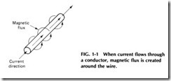
When current flows through a coil, a magnetic field with a north and a south pole is set up just like that of a permanent magnet. However, when the current stops, the magnetic field also disappears. This type of temporary magnetism is called electromagnetism. Permanent magnets are used for the magnetic field necessary in the operation of small, inex pensive electrical motors. Larger motors, relays, and transformers rely upon the magnetic fields from electrical current passing through coils.When electricity flows through a wire or conductor, magnetic lines of force (magnetic flux) are created around the wire as shown in Fig. 1-1
When a piece of wire is passed through a magnetic field (magnetic lines of force), electricity is created in that wire. We then can readily see the rela tion between electricity and magnetism. In fact, the very existence of the electrical industry is dependent on magnetism and magnetic circuits.
ELECTROMAGNETIC INDUCTION
Whenever a wire or other conductor is moved in a magnetic field so that the conductor cuts across the lines of force, there is an electromotive force produced in that conductor. If a conductor remains stationary and the magnetic field moves so that its lines cut across the conductor, an electromotive force is produced; “inducing” electromotive force by move ment between a conductor and a magnetic field is called electromagnetic induction.
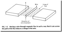
If a piece of wire is moved through magnetic lines of force (see Fig. 1-2) so the wire cuts across the path of the flux, a voltage will be induced in this wire. If a sensitive meter is then connected to this wire-complet ing the circuit-the dial will indicate a flow of current every time the wire is moved across the lines of force.
Referring again to Fig. 1-2, if the wire is moved upward through the flux, the meter will read to the left of zero, assuming the zero mark is in the center of the scale. If the wire is moved downward through the flux, the needle or indicator will read to the right of zero. Should the wire be moved rapidly up and down through the flux, the needle will swing back and forth- to the left and right of the zero mark. From this experiment it can be seen that the direction of the induced voltage and resulting cur rent flow depends on the direction of movement through the magnetic field and that both voltage and current can be reversed merely by revers ing the direction of movement of the wire. If the wire is held in the mag netic flux with no movement, no voltage will be generated. Or if the wire
is moved to the right or left-parallel to the path of the flux-no voltage will be produced. The wire must cut across the flux path to generate voltage- in other words, cutting the lines of force.
The faster the wire is moved through the magnetic field or the stronger the field and greater the number of lines of force, the more voltage will be generated. Therefore, the amount of voltage produced by electromagnetic induction depends on the speed with which lines of force are cut or the number of lines cut in a given period of time.
For example, one conductor cutting 100 million (100,000,000) lines of force per second will produce 1V of pressure. This obviously is an enor mous number of lines to cut to produce 1 V of electricity. However, by speeding up the movement of the conductor, as in an actual generator, the conductor will pass many poles per second, causing a higher voltage. The voltage may also be increased by connecting several wires in series in the form of coils.
For example, three separate wires moved upward through the flux at the same time causes an equal amount of voltage to be induced in each, all in the same direction. Then, when all are connected in series so their voltages will all add up in the same direction in the circuit, there will be three times as much voltage as with one wire. Generator coils are often made with many hundreds of turns connected in series to produce a very high voltage.
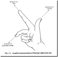
The direction of the induced voltage depends on the direction of the flux and on the direction in which the conductor is moved. One way to determine the direction of induced voltage when the directions of the mo tion and of the flux are known is to apply Fleming’s right-hand rule:
If the thumb of the right hand is pointed in the direction of the motion and the forefinger is pointed in the direction of the flux, the middle finger will be pointing in the direction of the generated voltage.
The position of the right hand when the conductor is moved upward is shown in Fig. 1-3. When the conductor is moved downward, the posi tion of the hand must be changed so that the thumb points downward; in this case, the middle finger will point forward, indicating a reversed voltage.
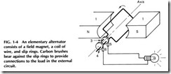
An elementary alternator is shown in Fig. 1-4. A stationary perma nent magnet 1, called a field magnet, with the poles N and S (north and south) provides the magnetic field. A rectangular coil of wire 2 is con nected to the slip rings 3 and 4, and both the coil and the rings are mounted on a shaft, not shown, which is caused to rotate by some outside source of mechanical power. Stationary pieces of carbon, called brushes, 5 and 6, bear against the slip rings and provide connections to the load 7 in the external circuit.
When the coil is rotated in either direction, a voltage is induced in this coil, but this voltage changes direction every half revolution.
Assume that the coil in Fig. 1-4 is rotating counterclockwise be tween the poles as indicated by the curved arrow. The lower side of the coil is moving upward toward the pole center, and so, according to Flem ing’s right-hand rule, the induced voltage is in the direction of the arrow,or toward the back of the machine. At the same time, the upper side of the coil is moving downward, also cutting the lines of force, and the voltage induced in this side is toward the front, as indicated by the arrow. When the coil is connected through the slip rings and brushes to the out side load, a current starts to flow in the circuit in the direction indicated by the arrows: toward the back in the lower side of the coil, around the coil back, through the upper coil side toward the front, through slip ring 3 and brush 5 to the load, and then to brush 6 and slip ring 4 and back to the coil. At one particular instant, the voltages induced in the two sides of the coil have such directions that the current flows in the same direc tion in all parts of the circuit.
As the coil approaches the center of the poles, the induced voltage increases because more lines of force are cut. The maximum voltage is reached as the coil sides pass the horizontal position. As the rotation con tinues, the coil sides cut fewer lines of force, and the induced voltage decreases until it reaches zero value when the coil is in an upright posi tion and does not cut any lines of force. As the coil continues to rotate, the direction of the voltage in each coil side reverses, because the side which moved upward before now moves downward, and the side which moved downward before now moves upward. The current through the load circuit now flows in the direction opposite to that indicated by the arrows in Fig. 1-4. The voltage first reaches a maximum in value and then decreases to zero when the coil is in an upright position between the poles. If the coil continues to rotate, the same process is repeated for every revolution.
The changes of induced voltage during one revolution are called one cycle. In each half of the cycle the voltage changes its direction and is, therefore, an alternating voltage, or ac voltage. If the machine is built so that there are 60 cycles during 1s, it is said that the voltage and the cur rent have a frequency of 60 cps.
POWER AND ENERGY
Energy, in brief, means ability to do work. Mechanical work is done when any kind of energy is used to produce motion in a body formerly station ary, or to increase the rate of motion of a body, or to slow down its rate of motion.
The most generally used unit of work is the foot-pound, which is when a mass of 1 lb is lifted 1 ft against the force of gravity. The total amount of work done is equal to the number of feet of motion multiplied by the number of pounds moved. Time doesn’t enter into the matter of mechanical work.
MECHANICAL POWER. Power is the rate of doing work involv ing work and time. One of the units in which power may be measured is foot-pounds per second. Power is equal to the total amount of work di vided by the time taken to do the work. It is assumed that the work is be ing done at a uniform or constant rate, at least during the period of time measured.
The foot-pound per second is a unit too small to be used in practice. Mechanical power most often is measured in the unit called a horsepower. One horsepower is the power rate corresponding to 550 ft·lb/s. Since there are 60 s in a minute, 1 hp also corresponds to 550 times 60, or to 33,000 ft •lb/min.
An electric power at the rate of 1 hp would be capable of raising a weight of 33,000 lb through a distance of 1ft in 1min. At the same rate of 1 hp the motor would lift during 1 min any number of pounds through a distance such that the pounds times the number of feet equaled 33,000.
ELECTRIC POWER. For an electric motor to continue working at the rate of 1 hp, an electric current must be sent through the motor at a certain number of amperes when the pressure difference across the motor terminals is a certain number of volts. The number of amperes and the number of volts would have to be such that multiplied together they would equal 746. A unit of electric power to describe this product of amperes and volts is called the watt. One watt is the power produced by a current of 1A when the pressure difference is 1V.
The total number of watts of power is equal to the number of amperes of current multiplied by the number of volts of pressure differ ence, both with reference to the device in which power is being produced. The number of volts must be 746 to produce 1 hp, so 746 W of electric power is equivalent to 1mechanical hp.
One watt-hour of electric energy is the quantity of energy used with a power rate of 1 W when this rate continues for 1 h. That is, the watt hours of energy are equal to the number of watts multiplied by the number of hours during which power is used at this rate. A 60-W electric lamp uses power at the rate of 60 W so long as it is lighted to normal bril liancy. But the total quantity of energy used by the lamp depends also on the total length of time it remains lighted. If the 60-W lamp is kept lighted for 10 h, it will have used 60 X 10, or 600 W • h of electric energy.


