Objectives
After studying this unit, the student will be able to:
• List applications of de motors
• Describe the electrical characteristics of de motors
• Describe the field structure of a de motor
• Change the direction of rotation of a de motor
• Identify the series and shunt fields and the armature winding with an ohmmeter
• Connect motor leads to form a series, shunt, or compound motor
• Describe the difference between a differential and cumulative compound motor
APPLICATION
De motors are used in applications where var iable speed and strong torque are required. They are used for cranes and hoists when loads must be started slowly and accelerated quickly. De motors are also used in printing presses, steel mills, pipe forming mills, and many other industrial applica tions where speed control is important.
SPEED CONTROL
The speed of a de motor can be controlled by applying variable voltage to the armature or field. When full voltage is applied to both the armature and the field, the motor operates at its base or nor mal speed. When full voltage is applied to the field and reduced voltage is applied to the armature, the motor operates below normal speed. When full voltage is applied to the armature and reduced voltage is applied to the field, the motor operates above normal speed.
MOTOR CONSTRUCTION
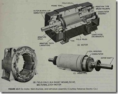
The essential parts of a de motor are the armature, field windings, brushes, and frame, figure 43-1.
The Armature
The armature is the rotating part of the mo tor. It is constructed from an iron cylinder that has slots cut into it. Wire is wound through the slots to form the windings. The ends of the wind ings are connected to the commutator which con sists of insulated copper bars and is mounted on the same shaft as the windings. The windings and commutator together form the armature.
Carbon brushes, which press against the commutator segment, supply power to the armature from the de power line. The commutator is a me chanical switch which forces current to flow through the armature windings in the same direc tion. This enables the polarity of the magnetic field produced in the armature to remain constant as it turns.
Armature resistance is kept low, generally less than one ohm. This is because the speed reg ulation of the motor is proportional to the arma ture resistance. The lower the armature resistance, the better the speed regulation will be. Where the brush leads extend out of the motor at the termi nal box, they are labeled AI and A2.
Field Windings
There are two types of field windings used in de motors: series, and shunt. The series field is made with a few turns of large wire. It has a low resistance and is designed to be connected in series with the armature. The terminal markings, Sl and S2, identify the series field windings.
The shunt field winding is made with many turns of small wire. It has a high resistance and is designed to be connected in parallel with the ar mature. Since the shunt field is connected in par allel with the armature, line voltage is connected across it. The current through the shunt field is, therefore, limited by its resistance. The terminal markings for the shunt field are Fl and F2.
IDENTIFYING WINDINGS
The windings of a de motor can be identified with an ohmmeter. The shunt field winding can be identified by the fact that it has a high resis tance as compared to the other two windings. The
series field and armature windings have a very low resistance. They can be identified, however, by turning the motor shaft. When the ohmmeter is connected to the series field and the motor shaft is turned, the ohmmeter reading will not be affected. When the ohmmeter is connected to the armature winding and the motor shaft is turned, the reading will become erratic as the brushes make and break contact with different commutator segments.
TYPES OF DC MOTORS
There are three basic types of de motors: the series, the shunt, and the compound. The type of motor used is determined by the requirements of the load. The series motor, for example, can pro duce very high starting torque, but its speed reg ulation is poor. The only thing that limits the speed of a series motor is the amount of load con nected to it. A very common application of a series motor is the started motor used on automobiles. Shunt and compound motors are used in applica tions where speed control is essential.
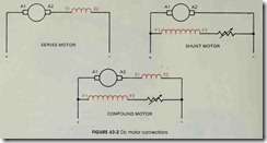
Figure 43-2 shows the basic connections for series, shunt, and compound motors. Notice that the series motor contains only the series field connected in series with the armature. The shunt mo tor contains only the shunt field connected parallel to the armature. A rheostat is shown connected in series with the shunt field to provide above normal speed control.
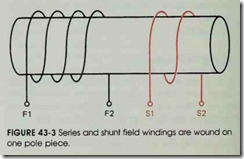
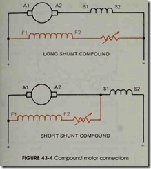
The compound motor has both series and shunt field windings. Each pole piece in the motor will have both windings wound on it, figure 43-3. There are different ways of connecting compound motors. For instance, a motor can be connected as a long shunt compound or as a short shunt com pound, figure 43-4. When a long shunt connection is made, the shunt field is connected parallel to both the armature and the series field. When a short shunt connection is made, the shunt field is connected parallel to the armature, but in series with the series field.
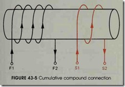
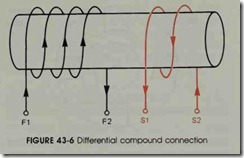
Compound motors can also be connected as cumulative or differential. When a motor is con nected as a cumulative compound, the shunt and series fields are connected in such a manner that as current flows through the windings they aid each other in the production of magnetism, figure 43-5. When the motor is connected as a differen tial compound, the shunt and series field windings are connected in such a manner that as current
flows through them they oppose each other in the production of magnetism, figure 43-6.
DIRECTION OF ROTATION
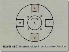
The direction of rotation of the armature is determined by the relationship of the polarity of the magnetic field of the armature to the polarity of the magnetic field of the pole pieces. Figure 43-7 shows a motor connected in such a manner that the armature will rotate in a clockwise direc tion due to the attraction and repulsion of mag netic fields. If the input lines to the motor are re versed, the magnetic polarity of both the pole pieces and the armature will be reversed and the motor will continue to operate in the same direc tion, figure 43-8.
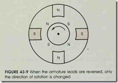
To reverse the direction of rotation of the ar mature, the magnetic polarity of the armature and the field must be changed in relation to each other . In figure 43-9, the armature leads have been changed, but the field leads have not. Notice that the attraction and repulsion of the magnetic fields now cause the armature to turn in a counterclock wise direction.
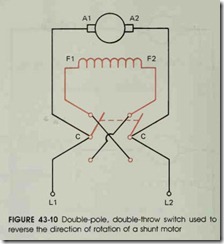
When the direction of rotation of a series or shunt motor is to be changed, either the field or the armature leads can be reversed. Many small de shunt motors are reversed by reversing the con nection of the shunt field leads. This is done be cause the current flow through the shunt field is much lower than the current flow through the ar mature. This permits a small switch, instead of a large solenoid switch, to be used as a reversing switch. Figure 43-10 shows a double-pole, double throw (DPDT) switch used as a reversing switch. Power is connected to the common terminals of the switch and the stationary terminals are cross connected.
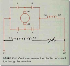
When a compound motor is to be reversed, only the armature leads are changed. If the motor is reversed by changing the shunt field leads, the motor will be changed from a cumulative com pound motor to a differential compound motor. If this happens, the motor speed will drop sharply when load is added to the motor. Figure 43-11 shows a reversing circuit using magnetic contac tors to change the direction of current flow through the armature. Notice that the direction of current flow through the series and shunt fields remains the same whether the F contacts or the R contacts are closed.
STANDARD CONNECTIONS
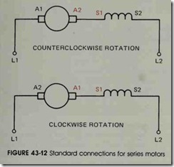
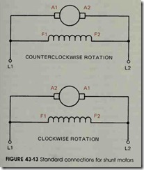
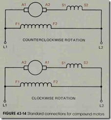
When de motors are wound, the terminal leads are marked in a standard manner. This per mits the direction of rotation to be determined when the motor windings are connected. The di rection of rotation is determined by facing the commutator end of the motor, which is generally located on the rear of the motor, but not always. Figure 43-12 shows the standard connections for a series motor, figure 43-13 shows the standard con nections for a shunt motor, and figure 43-14 shows the standard connections for a cumulative com pound motor.
REVIEW QUESTIONS
1. How can a de motor be made to operate below its normal speed?
2. Name the three basic types of de motors.
3. Explain the physical difference between series field windings and shunt field windings.
4. The speed regulation of a de motor is proportional to what?
5. What connection is made to form a long shunt compound motor?
6. Explain the difference between the connection of a cumulative compound and a differential compound motor.
7. How is the direction of rotation of a de motor changed?
8. Why is it important to reverse only the armature leads when changing the rotation of a compound motor?
