Capacitors are key components of AC circuits. Capacitors combined with resistors and inductors form useful electronic networks.
Capacitors in AC Circuits
When an AC voltage is applied to a capacitor, it gives the appearance that electrons are flowing in the circuit. However, electrons do not pass through the dielectric of the capacitor. As the applied AC voltage increases and decreases in amplitude, the capacitor charges and discharges. The resulting movement of electrons from one plate of the capacitor to the other represents cur- rent flow.
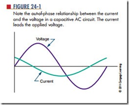
The current and applied voltage in a capacitive AC circuit differs from those in a pure resistive circuit. In a pure resistive circuit, the current flows in phase with the applied voltage. Current and voltage in a capacitive AC circuit do not flow in phase with each other (Figure 24-1). When the voltage starts to increase, current is at maximum because the capacitor is discharged. As soon as the capacitor charges to the peak AC voltage, the charging current drops to . As the voltage begins to drop, the capacitor begins discharging. The current begins to increase in a negative direction. When the current is at maximum, the voltage is at 0. This relationship is described as 90° out of phase. The current leads the applied voltage in a capacitive circuit. The negative voltage peaks when the voltage equals 0 volts. The phase difference continues through each cycle. In a purely capacitive circuit, the current leads the voltage by an angle of 90°. This can be represented by the acronym iCE. Current (I) leads the voltage (E) in a capacitive (C) circuit.
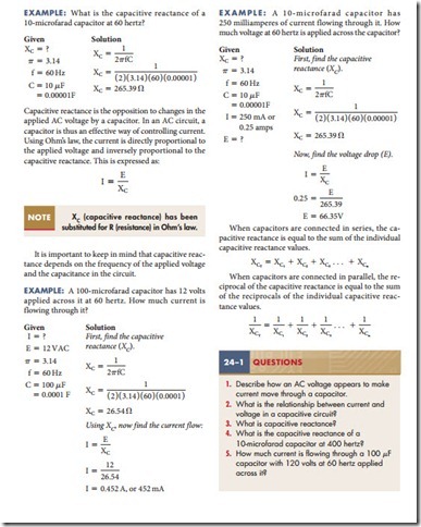
In a capacitive AC circuit, the applied voltage is constantly changing, causing the capacitor to charge and discharge. After the capacitor is initially charged, the voltage stored on its plates opposes any change in the applied voltage. The opposition that the capacitor offers to the applied AC voltage is called capacitive reactance. Capacitive reactance is represented by XC and is measured in ohms.
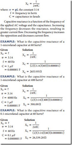
Capacitive reactance can be calculated by using the formula:


