Digital to analogue conversions
Conversion from digital to analogue signals must use methods that are suited to the type of digital signal that is being used. If, for example, a simple digital amplitude modulation were being used, or even a system in which the number of 1s were proportional to the amplitude of the signal, the conversion of a digital signal to an analogue signal would amount to little more than smoothing. As it happens, it is possible to convert a digital signal into a form that can be smoothed simply, and this is the basis of bitstream methods, noted later in this chapter. For the moment, however, it is more useful to concentrate on the earlier methods.
Smoothing always plays some part in a digital to analogue conversion, because a converted signal will consist of a set of steps, as Figure 9.18 shows, rather than a smooth wave. With a fast sampling rate, however, the steps are close spaced, and very little smoothing is needed. Even a crude resistor-capacitor smoothing circuit can work wonders with such a wave, and the more complex integrators can reproduce the analogue signal very faithfully, often closer to the original than is possible when a purely analogue method has been used. The faster the pulse-rate of the output of the D-A converter, the easier it is to smooth into an acceptable analogue signal.
The pulse code type of digital system does not allow a set of digital signals
to be converted into an analogue signal by any simple method, however. Remember that the digital signal consists of a set of digitally coded numbers that represent the amplitude of the analogue signal at each sampling point. The circuits that are used for conversion to analogue will convert each number into a voltage amplitude that is proportional to that number. The nature of the conventional conversion requirement is more easily seen if it is illustrated using a 4-bit number. In such a number (like any other binary number), each 1 bit has a different weighting according to its position in the number, so that 0001 represents one, 0010 is two, 0100 is four and 1000 is eight.
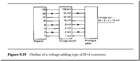
The progression is always in steps of two, so that if a register were connected to a voltage generator in the way illustrated for an 8-bit converter in Figure 9.19, each 1 bit would generate a voltage proportional to its importance in the number. In this way, a 1 in the second place of a number would give, say, 2 mV, and a 1 in the fourth place would give 8 mV, with a 1 in the seventh place giving 64 mV. Adding these voltages would then provide a voltage amplitude proportional to the complete digital number, 74 mV in this simple example. This, in essence, is the basis of all D-A converters.
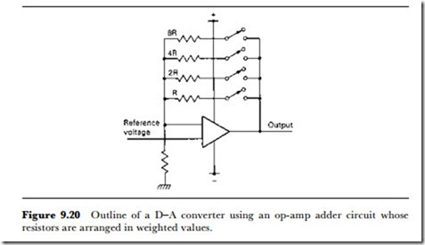
Reverting to a 4-bit number, Figure 9.20 shows the basis of a practical method. Four resistors are used in a feedback circuit which makes the output of the buffer amplifier depend on the voltage division ratio. This in turn is determined by the resistor ratio, so that switching in the resistors will give changes in voltage that are proportional to resistor value. In this example, each resistor can be switched into circuit by using an analogue switch, and the switches are in turn controlled by the outputs from the bits of a parallel output register. If the highest order bit in the register is a 1, the resistor whose value is marked as R is switched in, if the next bit is 1, then resistor 2R is switched in and so on.
The result of this is that the voltage from the output of the buffer amplifier (an analogue adder circuit) will be proportional to the size of the digital number. The attraction of this method is its simplicity – and that is
also its main problem. The resistor switching type of converter is widely used and very effective, but only for a limited number of bits. The problems that arise are the range of resistance that is required, and the need for quite remarkably precise values for these resistors. Suppose, for example, that the circuit can use a minimum resistance value of around 2 k1. This is a reasonable value, assuming that the amplifier has an output resistance that is not negligible and that the resistance values must be large compared with the resistance of the analogue switch when it is on. Now each resistor in the arrangement will have values that rise in steps of two, so that these values are 4 k1, 8 k1, 16 k1 … all the way to 256 k1 for an 8-bit converter.
Even this is quite a wide range, and the tolerance of the resistor values must also be tight. In an 8-bit system, it would be necessary to distinguish between levels that were one 256th of the full amplitude, so that the tolerance of resistance must be better than one in 256. This is not exactly easy to achieve, even if the resistors are precisely made and hand-adjusted, and it becomes very difficult if the resistors are to be made in IC form. The problem can be solved by making the resistors in a thick-film network, using computer-controlled equipment to adjust the values, but this, remember, is only for an 8-bit network.
When we consider a 16-bit system, the conversion looks quite impossible. Even if the minimum resistance value is reduced to around 1 k1, the maximum will then be of the order of 65 M1, and the tolerance becomes of the order of 0.006%. The speed of conversion, however, can be very high, and for some purposes a 16-bit converter of this type would be used, with the resistors in thick-film form and adjusted for precise value. For any mass-produced application this is not really a feasible method. The requirement for close tolerance can be reduced by carrying out the conversion in 4-bit units, because only the highest order bits require the maximum precision.
CURRENT ADDITION
The alternative to adding voltages is the addition of currents. Instead of converting a 16-bit number by adding 16 voltages of weighted values (each worth twice as much as the next lower in the chain), we could consider using 65 535 current sources, and making the switching operate from a decoded binary number.
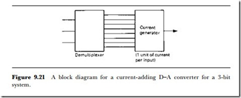
Once again, it looks easier if we consider a small number, three digits this time, as in Figure 9.21. The digital number is demultiplexed in a circuit that has eight outputs. If the digital number is 000, then none of these outputs is high; if the digital number is 001, then 1 output is high; if the digital number is 010, then two outputs are high; and if the digital number is 011, then three outputs are high; and so on. If each output from this demulti- plexer is used to switch an equal amount of current to a circuit, the total current will be proportional to the value of the binary number.
The attraction of this system is that the requirement for precise tolerance is much less, since the bits are not weighted. If one current is on the low side, another is just as likely to be on the high side, and the differences will cancel each other out, something that does not happen if, for example, the one that is low is multiplied by 2 and the one that is high is multiplied by 1024. The effort of constructing 65 535 current supplies, each switched on or off by a number in a register, is not quite so formidable as it would seem in the current state of IC construction.
The main compromise that is usually made is in the number of currents. Instead of switching 65 535 identical current sources in and out of circuit, a lower number is used, and the current values are made to depend on the place value of bits. Suppose, for example, that 16 383 currents are to be used, but that each current could be of 1, 2, 4 or 8 units. The steps of current could be achieved by using resistors whose precision need not be
too great to contemplate in IC form, and the total number of components has been drastically cut, even allowing for the more difficult conversion from the digital 16-bit number at the input to the switching of the currents at the output. This is the type of D-A converter that is most often employed in fast-working converters.
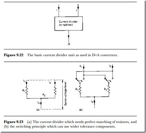
Another possibility is to use a current analogue of the resistor switching method used in the voltage step system, so that the currents are weighted in 2:1 steps, and only 16 switch stages are needed. This is feasible because current dividers can be manufactured in IC form. The principle of a current divider is shown in Figure 9.22, with currents shown as flowing into the terminals at the top rather than out. The distinction between a current adder and a current divider depends on the direction of current. To act as a precise divider, however, the input currents must be identical to a very close tolerance, and this cannot be achieved by a resistive network alone.
In this form of converter, first described by Plassche in 1976, the resistor network is used along with current switching. The principle is shown in Figure 9.23, and is easier to think of as a current adder rather than a
divider. The two input currents I1 and I2 form the current I3, and if the resistors R1 and R2 are equal, then I1 = I2 = I3/2, giving the condition (I1 or I2) being exactly half of the other current I3. The snag, of course, is that resistors R1 and R2 will not be identical, particularly when this circuit is constructed in IC form.
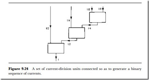
The ingenious remedy is to alter the circuit so that each current is chopped – switched so that it flows alternately in each resistor. For one part of the cycle, I1 flows through R1 and I2 through R2, then in the other part of the cycle, I1 flows through R2 and I2 through R1. If the switching is fast enough and some smoothing is carried out, the differences between the resistor values are averaged out, so that the condition for the input currents I1 and I2 to be exactly half of I3 can be almost met even if the resistors are only to about 1% tolerance. Theory shows that the error is also proportional to the accuracy of the clock that controls the switching, and this can be made precise, to better than 0.01% with no great difficulty. Now if a set of these stages is connected as in Figure 9.24, the ratio of currents into the stages follows a 2:1 step, and this can be achieved without a huge number of components and without the requirement for great precision in anything other than a clock signal to control switching. In addition, the action of the circuit can be very fast, making it suitable for use in the types of A-D converter that were discussed above. The only component that cannot be included into the IC is the smoothing capacitor that is needed to remove the slight current ripple that will be caused by the switching. This can be an external component connected to two pins of the IC.
The level of conversion is another point that needs to be considered. If we take a voltage conversion as an example, the amplitude of the signal steps will determine whether the peak output is 10 mV, 100 mV, 1 V or whatever. The higher the peak output, the more difficult is the conversion because switching voltages rapidly is, in circuit terms, much simpler when the voltage steps are small, since the stray capacitances have to be charged to lower levels. On the other hand, the lower the level of the conversion, the greater the effect of stray noise and the more amplification will be needed. A conversion level of about 1 V is ideal, and this is the level that is aimed at in most converters.
CONVERSION PROBLEMS
The problems that arise with the conventional type of D-A converter are closely connected with the nature of the digital signal and the ever-present problems of precise current generation. A 16-bit D-A converter requires the use of 16 current sources, and the ratio of a current to the next lower step of current must be exactly 2. For a conventional type of current generator system in which the current source provides current I, the most significant bit will be switching a current equal to I/2 and the least signifi- cant bit will be switching a current equal to I/65 536. With all switches open (all bits zero), the current will be zero; with all switches closed (all bits 1), the current will be equal to I – I/65 536. Note that the current can never be equal to I unless the number of bits is infinite; in this example, I/ 65 536 is the minimum step of current. The value of I/2 is taken as being the current corresponding to zero signal, so that zero is being represented by 1000000000000000 – current converters cannot deal with negative currents.
Maintaining the correct ratios between all of these currents is virtually impossible, although many ingenious techniques have been devised. In particular, this scheme of D-A conversion is very susceptible to a form of cross-over distortion, when the zero current level changes to the minimum negative current. In digit form, this is the change from the current I/2 (represented by the digital number 1000000000000000) to the value which is the sum of all the current from I/4 down to I/65 536, corresponding to the digital number 0111111111111111. This step of current ought to be small, equal to I/65 536, but if any of the more significant current values are incorrect even to the extent of only 0.05%, the effect on this step amount will be devastating – a rise of seven times the minimum current instead of a fall of the minimum step amount, for example.
This amount of error is virtually unavoidable, and it will cause a cross- over error to occur each time the signal passes through the zero level, corresponding to a current of I/2. In addition to this cross-over problem, all converters suffer from ‘glitches’, which are transient spikes that occur as the bits change. These are caused by small variations in the time when switches open and close, and they are also most serious when the signal level is at its minimum, because they cannot be masked by the signal level, and the number of bits that change is at its greatest when there is a change
from zero (I/2 current) to a small negative value. Both of these problems are answered by the adoption of bitstream methods.
OVERSAMPLING
The sampling of an analogue signal creates a set of pulses which are still amplitude modulated and which correspond to the analogue signal plus a set of sidebands around the sampling frequency and its harmonics. After the D-A converter has done its work, this is the signal that will exist at the output and it requires low-pass filtering to reject the higher frequencies.
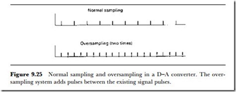
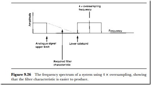
This, however, calls for the use of filters with a very stringent specification, and such filters have an effect on the wanted part of the frequency range that is by no means pleasant. A simple way out of the problem would be to double the sampling rate. This is always feasible, since A-D converters are stretched as it is to cope with high-frequency signals. What can be done, though, is to add pulses between the output pulses from the A-D converter (Figure 9.25). This creates a pulse stream at double the original rate, and so makes the frequency spectrum quite different (Figure 9.26). This now makes the lowest sideband well above the limit of the wanted signal and easily filtered out. In addition, if the added pulses are midway in amplitude between the original pulses, interpolated values, the conversion from pulses to smoothed audio can be considerably smoother, just as if the real sampling rate had been doubled. Oversampling of four times or even more is now quite common.
BITSTREAM METHODS
The most significant development in digital conversion in recent years has been the use of bitstream technology. The output of a bitstream converter is not the voltage or current level that is the output of a conventional D-A converter but, as the name suggests, a stream of 0s and 1s in which the ratio of 1s to 0s represents the ratio of positive to negative in the analogue
signal. For example, a bitstream of all 1s would represent maximum positive voltage, one of all 0s would represent maximum negative voltage, and one of equal numbers of 1s and 0s alternated would represent zero voltage.
The enormous advantages of bitstream conversion are that only one current generator is required, there are no ladder networks needed to accomplish impossibly precise current division, and the output signal requires no more than a low-pass filter – the bitstream signal is at such a high frequency that a suitable filter is very simple to construct. The disad- vantage is that the system must at this point handle high frequencies – of the order of 11-33 MHz for the bitstream converters now being used for audio-frequency signals. The essence of the bitstream converter is that instead of using a large number of levels at a relatively slow repetition rate, it uses very few levels (two) at a much higher repetition rate. The rate of information processing is the same, but it is accomplished in a very different way.
The principles are surprisingly old, based on a scheme called delta modulation which was developed for long-distance telephone links in the 1940s and 1950s. The normal pulse-code modulation system of sampling and converting the amplitude of the sampled signal into a binary-coded number has well-known drawbacks due to the noise that is generated because of the quantization process.
Delta modulation uses the difference between samples, which is converted into binary numbers. If the rate of sampling is very high, the difference between any consecutive pair of samples is very small, and it can be reduced to 1 bit only. A signal of this type can be converted back to analogue by using an integrator and a low-pass filter. Because of the very severe distortion that occurs when a delta modulator is overloaded, the sigma delta system was developed. This uses sampling of the signal
amplitude rather than differences, and forms a stream of pulses by a feedback system, feeding the quantified signal back to be mixed with the incoming samples in an integrator. This results in a noise signal which is not white noise, spread evenly over the whole range of frequencies, but coloured noise, concentrated more at the higher frequencies. Because of this characteristic, this type of modulator is often termed a noise-shaper. This is the type of technology, used on other digital systems, which has led to bitstream and other forms of D-A converters in which the number of bits in the signal is reduced.
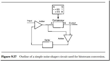
Current bitstream D-A converters consist basically of an oversampling stage followed by the circuit called the noise-shaper. The oversampling stage generates pulses at the correct repetition rate, and the noise-shaper uses these pulses to form a stream of 1s and 0s at the frequency determined by the oversampling rate. The important part of all this is the action of the noise-shaper. Figure 9.27 shows the principles of a noise-shaper, which consists of two adders, a converter, and a delay – the amount of the delay is the time between pulses. If we concentrate on the converter for the moment, this is a circuit which has a very fast response time and which will give an output of 0 for numbers corresponding to less than half of full output, and an output of 1 for numbers corresponding to more than half of the maximum level. The generation of the bitstream is done rather like the conversion of a denary number into binary, by successive comparisons giving a 0 or 1 and feeding the remainder of a comparison back to be sub- tracted from the next (identical) input signal. Note that 0 and 1 from the converter corresponds to 0 or Imax current values in a conventional D-A circuit rather than the digital 0 and 1 of a number.
Imagine a number at the input causing either a 0 or a 1 signal to be developed. The second adder works with one inverted signal, so that its output is the difference between the original signal amplitude number and
the maximum signal (output 1) or minimum signal (output 0). This differ- ence is delayed so that it appears at the input adder while the same over- sampled copy of the input is still held there – the amount of delay will fix how many times this action can be carried out on each input. If the error signal is negative, it will be subtracted from the input, otherwise it is added, and the result is fed to the converter. This again will result in a maximum or minimum output signal and an error difference, and the error difference is once again fed to the input adder to be added to the new input and so to be converted. At each step, the output is a 1 or a 0 at many times the pulse repetition rate of the oversampled signal, and with the ratio of 0s and 1s faithfully following the amplitude corresponding to the input numbers.
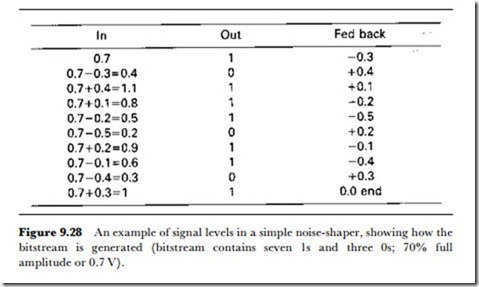
Figure 9.28 illustrates the principle. The input number represents an amplitude of 0.7 and this input will cause the converter to issue an output of 1. The difference is -0.3, and when this is added to the next identical input it gives a net input of 0.4 which causes a 0 output with an error of +0.4. The diagram shows the successive steps which end when the net input to the converter is 1, so that there is no error signal from the output – this ends the conversion which, in this example, has taken 10 steps – implying that the output frequency will be 10 times the input frequency. The output is a stream of seven 1s and three 0s, corresponding to a wave that is 70% full amplitude or has an amplitude of 0.7 of the maximum.

