Electricity
If electricity seems more mysterious than some of our more prosaic tools like hammers and pliers, it is mainly because electricity is invisible. There is no way of seeing an electric current How through a wire.
But that does not mean that electricity is hard to understand. Nobody ever saw the wind, either. We see trees blowing or dust moving, and we take it for granted that there is an invisible force-a moving air current-causing these reactions. We can easily learn how to use this invisible current to sail a boat or fly a kite without bothering too much why the air current happened to be there. In the same way, we can learn to understand and use the invisible current we call electricity.
An electric current is simply a gale of electrons moving at the rate of thousands of miles per second. They How readily through a wire because the individual atoms are spaced at relatively vast distances.
There are multitudes of free or unattached electrons in the vast spaces between the atoms in the wire. When no current is flowing these electrons wander around haphazardly.
However, when the wire is connected into an electrical circuit, the voltage acts as an invisible force to drive these electrons through the wire at fantastic speeds, just as the invisible wind blows a cloud of leaves between the trees in a forest.
It is sufficient for our purpose to picture voltageas an invisible force which urges electrons to How through a wire. Thus voltage may be thought of as electrical pressure just as a wind is caused by air pressure. Note that the atoms in the wire offer resistance to the How of electrons just the same as a forest of trees offers resistance to flow of wind.
Whenever an eleetron is in motion it somehow surrounds itself with a proportionately small mag netic “field”. Therefore, whenever current flows through a wire, the billions of moving electrons produce a magnetic “field” surrounding the wire, the strength of the field being proportional to the amperage (that is, proportional to the number of electrons involved). This phenomenon of magne-
tism is of importance in connection with the vari ous electro-magnetic units on a car.
It was Benjamin Franklin who first realized that current How through a circuit had to be in one direction or the other and so he guessed that How was from positive to negative. Ever since that day it has been customary to speak of current flowing from positive to negative-and in practical electri cal work it is still customary to think of current flowing from positive to negative even though just the opposite is true.
Positive and negative terminals are frequently called plus ( + ) and minus ( -) terminals. Battery and generator terminals are marked with ( + ) and (-) signs to denote their polarity.
In an automobile, current is supplied to the various electrical units by either the storage bat tery or the generator. The generator is driven by the engine. When the engine is stopped, the bat tery supplies current to operate the starter, igni tion system, lights, hom and other units.
When the engine is running above a minimum speed corresponding to about 10 m.p.h. in high gear, current for the various electrical units is supplied by the generator. Equipped with an alternator, another type of generator, the engine at idle will supply sufficient current to more than meet its own ignition requirements. Hereafter, the term generator is meant to include both ordinary generators and alternators.
Usually the generator produces more current than is required for the electrical units and the excess flows to the battery where it is stored as chemical energy.
Some time later when current is needed when the engine is stopped, the chemical energy may be converted back into electrical energy and allowed to How to the various units in the electrical system.
A generator or battery does not create elec tricity . The electricity is always present in the form of the very small unit of electricity carried by each wandering electron. All a battery or gener ator does is to create the pressure that moves these hordes of electrons against the resistance of the circuit.
The action of a generator might be compared with an automobile fan. As the fan rotates, it creates a current of air by piling up air to the rear of the fan, creating a pressure, and sucking air away from the front of the fan, creating a suction.
We don’t have to know everything there is to know about the air or the fan to understand that these whirling blades will suck air in on one side of the fan and blow it out on the other.
Similarly, as the auto’s generator rotates, i creates a current of electrons, pushing them out at one terminal and sucking them in at the other. We don’t have to know all the physicist’s theories about electricity in order to picture that action.
The force or pressure which “blows” the current along its way is commonly expressed in volts. Volts are comparable to wind pressure.
Note that electricity, unlike a stream of water or air, will not flow unless there is a complete circuit from the generator or the battery out through the various electrical devices and then back to the
gener ator or battery again. Break the circuit any where and the current will stop flowing.
Suppose we connect up a lamp bulb and a car storage batt ery, as in Fig. 1. This forms a circuit, for the current of electrons flows in a complete circuit from the battery along one wire to the lamp, through the lamp filament, and back along th e other wir e to the battery again.
TYPES OF CIRCUITS
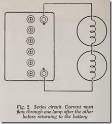
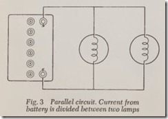
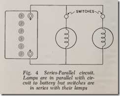
Ther e are three types of circuits: series, parallel and series-parallel. For example, if you wanted to hook up two lamps with an automobile battery, there are two ways in which you might do it, namely, in series and in parallel.
Series Circuit-In Fig. 2 the current must flow through one lamp, then through the other before returning to the battery. The two lamps are said to be connected in series.
Parallel Circuit-In Fig. 3 the current divides. Part of the current Bows through one lamp, while the remainder Bows through the other one. This is called a parallel circuit since there are two parallel paths for the current.
Series-Parallel Circuit-Fig. 4 shows a series parallel circuit. The lamps are in parallel but each switch is in series with its lamp.
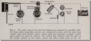
All three circuits are of great importance with respect to the electrical system of the automobile since all major units are in parallel with the bat tery and the generator, while the switch or relay controlling each unit is in series with the unit which it controls, Fig. 5.
ELECTRICAL MEASUREMENTS
A current flow of a certain number of amperes may be compared with the Bow of so many gal lons of water per minute through a pipe. Both amperes and gallons indicate the quantity flowing.
Pressure in pounds per square inch is used to force the water through the pipe while pressure in volts is required to force a current through a wire.
When water flows through a pipe some of the pressure is used to overcome the frictional resis tance offered by the pipe. A wire also offers resis tance to the Bow of electric current. The unit of resistance is the ohm.
Different metals vary greatly as to their resis tance. Copper has an exceptionally low resistance. Steel has 10 times the resistance of copper and cast iron 50 times. The resistance of copper cable used in an automobile is very small. For example, the resistance of No. 14 cable (about 1/16 inch in diameter) is only 1/1000 ohm per foot of length.
The resistance of a wire is proportional to its length. For example, the resistance of six feet of cable will obviously be six times the resistance of just one foot. It should also be obvious that resis tance varies according to the cross-sectional area of the wire or cable. In other words if the area of a wire is half what it should be then the resistance will be doubled for any given length of wire.
When renewing cables on a car be sure that the diameter of the metal cable is adequate. If the diameter is too small the flow of current will be throttled and the electrical unit to which the wire connects will not work properly. For example, a lamp will be less bright than it should be.
In a given circuit with a given resistance the amperes of current Bowing are proportional to the voltage. For example, if the voltage is doubled the amperage is also doubled.
Likewise, for example, if the battery provides 12 volts to deliver 2 amperes to a certain lamp circuit, a generator supplying 15 volts to this circuit will deliver 15/12 x 2 amperes or 2 amperes, making the light glow brighter than before.
The volt, ampere and ohm take their names from three early electrical researchers named Aile sandra Volta, Andre Ampere and George Ohm. The “size” of the volt, ampere and ohm have been so chosen that a pressure of one volt applied to a resistance of one ohm causes a current of one ampere to flow.
This relationship between volts, amperes and ohms may be simply expressed by the equation:
Volts= Amperes X Ohms
This equation is known as Ohm’s law. It may be used to nnd out how many volts are required to produce a current of so many amperes against a resistance of so many ohms. For example: How many volts are needed to force 6 amperes against a resistance of 2 ohms? Using the equation above we have:
Volts= 6 X 2 = 12
The equation may be transposed to permit the ohms resistance to be found when amperes and volts are known. As follows:
If we want to know the amperes when volts and ohms are known, the equation becomes:
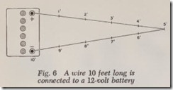
A fully charged battery provides approximately 12 volts at its terminals, considering only the new 12 volt automobile electrical systems and not the older 6 volt systems. In other words, a voltmeter connected across its terminals will read 12 volts. If we connect a wire to the two terminals, the volt age drops gradually ·from one end of the wire to the other, the total drop, of course, being 12 volts. For example, if the wire is 10 feet long, the voltage drop will be 12/10 volts per foot, as in Fig. 6; if 100 feet long, 12/100 volts per foot, and so on.
Therefore, let us assume that the 10 foot wire has a total resistance two ohms ( 2/10 or 1/5 ohm per foot), Fig. 6. Ohm’s law states that:
Battery voltage is 12 and the resistance of the wire is two ohms. Therefore, the current flowing through the wire is:
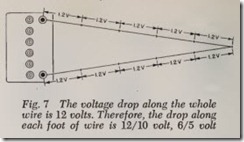
Remembering that the resistance of the wire per foot is 2/10, or 1/5, the voltage drop per foot is: 6 Amperes X 1/5 Ohm = 6/5 Volt
The voltage drop per foot is shown in Fig. 7.
The same wire is shown in Fig. 8 with volt meters connected in various ways to show the voltage drop between various points on the wire. The voltmeters are represented by circles and the voltage drop is indicated within the circle.
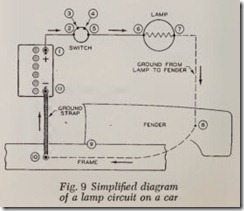
Fig. 9 shows a simplified lamp circuit with arrows indicating the flow of current. There are cable conductors from battery to switch, from switch to lamp and from the lamp to a ground on the front fender. From thence, current flows through the fender to the frame and along the frame to the ground strap, then through the ground strap back to the battery. Path of current through fender and frame is shown by a broken line.
There are 11 connections in this simplified cir cuit, numbered 1to 11. No. 8 repres ents the metal to-metal contact between fender and frame. There are two connections within the switch, designated by numbers 3 and 4. When all these connections are clean and tight the voltage drop at each con nection is negligible. Likewise the voltage drop in the conductors is negligible (including fender and frame). Therefore practically the entire 6 volts at the battery is available at the lamp and therefore the lamp glows with satisfactory brightness.
However, even slight looseness at any connection will increase the voltage drop at this point and thus rob the lamp of some of the voltage it needs.
A loose connection may also permit dust, lubricant and/or water to enter. Water permits corro sion, including rust. Dust, lubricant and corroded surfaces offer increased resistance to flow of cur rent. Voltage drop at these points may become sizable and proportionately diminish the bright ness of the lamp. If the surfaces at a connection are completely coated with dirt, lubricant and/or corrosion the resistance at such a point may be infinite with the result that no current whatever flows. In this case almost the entire voltage drop of the battery will occur across this connection.
A voltmeter is a most useful instrument to locate a loose or dirty connection-not forgetting a rusty fender-to-frame connection.
It should be remembered that 6 to 8 volts is such a low electrical pressure that even a slight amount of dirt may completely stop the flow of current.
What has just been said concerning the simpli fied lamp circuit, Fig. 9, is equally true of all the circuits in the car.
When current is drawn from the battery there is a drop of voltage across the battery terminals, the amount of drop being proportional to the amperes flowing. The drop is slight for moderate amounts of current-say 25 amperes or so. However, when the starter switch is closed, a large current ( 300 amperes or more) flows through the starter circuit and voltage across the battery drops to about 4
-a loss of 7 volts (still considering a 12-volt system). This drop is due to the fact that the current flow is so heavy that the battery is unable to maintain its voltage. In other words, its chemi cal processes are not fast enough to keep the voltage up where it should be.
In any electrical device it is the quantity of amperes which produces the result we are after. This remark holds true regardless of the type of device, whether it is a lamp, ignition coil, starting motor, cigarette lighter or what not. In every case, a certain amperage is required to do the job in hand. The necessary amperage is that called for by the size of the unit. So it should be obvious that a 100 watt bulb should require about twice the amperage of a 50 watt bulb if both are to glow with the same brilliancy. Likewise a 2 horsepower starting motor requires about twiee the amperage of a 1 horsepower motor. An ignition coil which needs 6 amperes will be much more powerful than a 4-ampcre coil. A 1 horsepower 6-volt starting motor can be made to produce 2 horsepower by applying 12 volts to it because doubling the volt age doubles the power. (The figures given in this paragraph arc true in principle. For simplicity any complicating factors which may alter our round number values are ignored, and it is not recom mended that the power of a starting motor be doubled by doubling the voltage.)
The preceding paragraph shows that electrical power depends on both volts and amperes. To be exact, electrical power equals:
Volts X Amperes =Watts
The watt is the unit of electrical energy and 746 watts are the equivalent of one horsepower.
The ampere and ohm are actually measured according to internationally accepted m ethods, while the volt is derived from Ohm’s Law.
One ampere is defined as th e (constant) cur rent required to electrolytically deposit .00025 pounds of silver per second when the current flows through a silver nitrate solution.
One ohm is the resistance offered at 32 degrees Fahrenheit by a column of mercury approximately 40 inches long having a uniform cross-sectional area of .0016 square inches.
One volt is the electrical pressure (electro motive force) required to cause a current of one ampere to flow against the one ohm resistance of the mercury column just mentioned.
The value of the volt is calculated from Ohm’s Law. In other words, after having determined the value of the ampere and the ohm as stated above, the value for the volt equals ampere times ohm, or:
1Volt= 1Ampere X 1Ohm
ELECTRICAL CONDUCTORS
In an automobile, five principal types of con ductors of electricity are used. These are wires, cables, straps, engine and chassis parts, and air (between the spark plug points). The term wire needs no definition. A cable consists of numerous strands of wire twisted together. A cable is obvi ously more flexible than a wire of the same diam eter. Therefore, it is easier to handle and not so likely to break. A strap, as its name implies, is flat. It is woven of strands of wire for the sake of flexibility. On some cars a strap instead of a cable is used to connect the battery to the frame or engine. If the battery is grounded on the frame a ground strap may also be used between engine and frame in order to make a good electrical connection between the two. Except for the ground strap (or straps), all the conductors on the car are insulated. Generally speaking the con ductor is enclosed in natural or synthetic rubber and then one or two layers of braided cotton or silk are added. Often in addition, the outer layer of braiding is lacquered. On high-tension cable, instead of covering the rubber with braiding and lacquer, the rubber may be enclosed in a rubber like synthetic material.
An electric current produces heat in the con ductors through which it moves. The larger the number of amperes flowing through a wire the hotter it gets. Also the greater the resistance in ohms the more the temperature of the wire rises.
The electric lamp is based on the principle just described. The lamp contains a slim filament of tungsten which is heated white hot by the amperes flowing through it. Tungsten is used because of its unusually high melting point ( 5000°F) which is twice that of steel.
The filament is designed to operate at a white hot temperature close to its melting point. The filament metal is so hot that it gradually vaporizes and in this way “wears out” until the filament becomes so thin it melts and breaks and then the – lamp must be replaced. Meanwhile the interior surface of the bulb is blackened by the condensa tion of the vaporized metal. The hotter the fila ment the more efficient it is as a light producer that is, the more light it emits for a given amper age. Hence it is good economics to operate the filament at such a very high temperature rather than reduce the temperature to increase the life of the filament. In short, the longer the filament life the more current is required for a given brilliancy of a lamp.
A slight reduction in voltage (and therefore amperage) delivered to the lamp results in a marked decrease in brilliance. Even a half volt reduction at the lamp will cause a large decrease in the amount of light produced. Hence the im portance of keeping. the lamp circuit connections clean and tight.
On the other hand, because the filament oper ates at a temperature close to its melting point, just a small increase in voltage above normal will vaporize the filament at a rapid rate and thus reduce lamp life to just a few hours or even to zero. For if there is sufficient increase in voltage the !).lament will melt instantly.
A cigarette lighter is based on the same prin ciple as the bulb. A coil of wire is heated red hot by an electric current.
In designing electrical units for an automobile the problem of temperature rise caused by current flow must be kept in mind. Wiring within the units must not become hot enough to damage the insulation. Hence the capacity of a unit, such as a generator, is limited by the practical question: will the production of more amperes singe the insula tion? And the same remark holds true for external wiring connecting the various units in the electri cal system. Overheating of insulation is mainly avoided by using wires of adequate size.
However, the generator is equipped with a fan which blows cooling air through its interior. In this way the generator is able to deliver a higher amperage without damage to the insulation than would be possible without the air cooling feature.
Review Questions
1. The movement of what kind of particles in a conductor results in an electric current? . . ..
2. When a wire is connected into a circuit, what electrical unit must be present to cause a flow of current?
3. What effect does an electron moving in a conductor have on its immediate sphere of in- fluence? …………………………………..
4. What is polarity in an electrical circuit? ……………………………
5. What is the true direction of current flow in an electrical circuit? ………………… .
6. Does the true direction of current flow agree with Benjamin Franklin’s observations? … .
7. What two units in an automobile’s electrical system supply electric power? …………. .
8. Do the sources of electric power in an automobile create electricity? …………….. .
9. What particular condition must exist in a circuit before current can flow through it? ….. .
10. Name three types of circuits …………………… . . . ……………….. . …… .
11. Which particular unit of electrical measurement might be compared to pressure in a water pipe ? . . ………………………
12. Which particular unit of electrical measurement might be compared to resistance in a water pipe? . ………………………………………..
13. Which particular unit of electrical measurement might be compared to rate of flow in a water pipe? …………………………….
14. Why I.S copper usedalmost exc us1ve y m w1.rmg.? . . ………………….. . ……… .
15. What is meant by the cross-sectional area of a wire? . . ……………………….. .
16. How does the cross-sectional area of a wire affect current flow? ………………… .
17. What is OHM’s law? …. . ………………….
18. Write the equation which expresses OHM’s law……………………………… .
19. Write the OHM’s law equation in the proper form to determine resistance when volts and amperes are known. . …………………………………….
20. Write the OHM’s law equation in the proper form to determine amperes when volts and resistance are known. . . . . . . . . . . . . . . . . . . . . . . . . . . . . .
21. What is voltage drop in a circuit? . . . . . . . . . . . . . . . . . . . . . . . . . . . . . . .
22. What factor in a circuit is responsible for voltage drop? . . . . . . . . . . . . . . . . . . . . . . . . .
23. Which instrument is most useful in locating loose or corroded electrical connections? . . .
24. What unit in an automobile’s electrical system causes the greatest voltage drop when in operation? ………………………..
25. What two factors are used to calculate wattage? . . . . . . . . . . . . . . . . . . . . . . . . . . . . . . . . . .
26. How many watts are equivalent to one horsepower? . . . . . . . . . . . . . . . . . . . . . . . . . . . . . .
27. What is the difference between a cable and a wire? . . . . . . . . . . . . . . . . . . . . . . . . . . . . . .
28. What is a strap as used in an automobile ‘s electrical system? . . . . . . . . . . . . . . . . . . . . . . . .
29. What characteristics of a bulb filament causes it to glow when current is passed through it?
30. Why is the generator on an automobile air cooled? . . . . . . . . . . . . . . . . . . . . . . . . . . . . . . . . . .

