BASIC INDUCTION MOTOR CONCEPTS
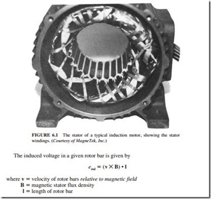
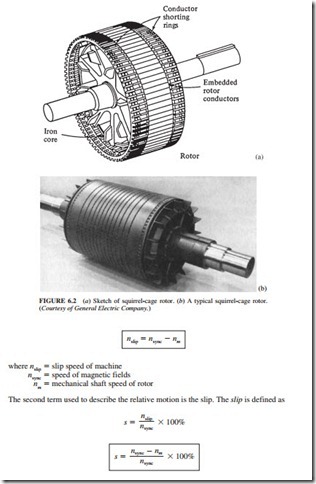
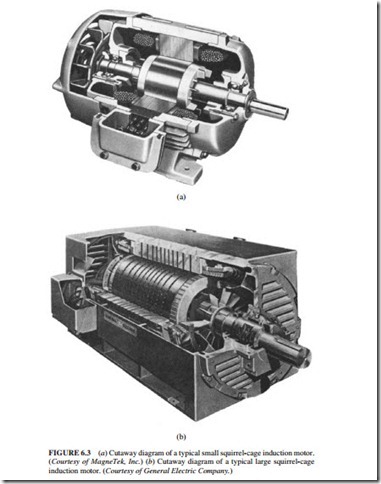
Figure 6.6 illustrates a squirrel-cage induction motor. A set of three-phase currents is flowing in the stator. A magnetic field BS is produced. It rotates in a counterclockwise direction.
where fe is the electrical frequency in hertz and P is the number of poles in the machine. The rotating magnetic field BS crosses the rotor bars and induces a voltage in them.
The voltage in a rotor bar is induced by the relative motion of the rotor compared to the magnetic field. The velocity of the upper rotor bars relative to the magnetic field is to the right. Therefore, the induced voltage in the upper bars is out of the page, and the induced voltage in the lower bars is into the page.
The current is flowing out of the upper bars and into the lower bars. However, the peak rotor current lags behind the peak rotor voltage due to the inductive nature of the rotor assembly. A rotor magnetic field BR is produced by the current flowing in the rotor. Since the induced torque is given by
the resulting torque is counterclockwise. The rotor accelerates in this direction.
The Concept of Rotor Slip
The speed of the rotor relative to the magnetic fields determines the voltage induced in the rotor. The relative speed is used because the behavior of the motor depends on the voltage and current in the rotor.
The two terms used to define the relative motion between the rotor and the magnetic fields are the slip speed and the slip. The slip speed is the difference between synchronous speed and rotor speed:
When the rotor turns at synchronous speed, s 0. When the rotor is stationary, s 1. All motor speeds fall between these two limits.
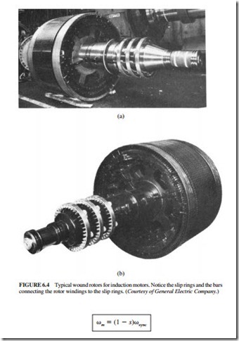
 The mechanical speed of the rotor shaft can be expressed in terms of the synchronous speed and slip as
The Electrical Frequency of the Rotor
Induction motors have been called rotating transformers because they work by inducing voltages and currents in the rotor. The primary (stator) induces a voltage in the secondary (rotor), but the secondary frequency is not necessarily the same as the primary frequency. If the rotor is locked, it will have the same frequency as the stator. If the rotor turns at synchronous speed, the frequency of the rotor will be equal to zero. For any speed in between,
