REPULSION-INDUCTION MOTOR
The repulsion induction motor starts on one principle of operation and, when almost up to speed, changes over to another type of operation. Very high twisting forces are produced during starting by the repulsion between the magnetic pole in the armature and the same kind of pole in the adjacent stator field winding. The repulsing force is controlled and changed so that the armature rotational speed increases rapidly, and if not stopped, would continue to increase beyond a practical operating speed. It is prevented by a speed actuated mechanical switch that causes the armature to act as a rotor that is electrically the same as the rotor in singlephase induction motors. That is why the motor is called a repulsion induction motor
The stator of this motor is constructed very much like that of a split phase or capacitor start motor, but there are only run or field windings mounted inside. End bells keep the armature and shaft in position and hold the shaft bearings
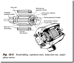
The armature consists of many separate coils of wire connected to segments of the commutator. Mounted on the other end of the armature are governor weights, which move pushrods that pass through the armature core. These rods push against a short circuiting ring mounted on the shaft on the commutator end of the armature. Brush holders and brushes are mounted in the commutator end bell, and the brushes, connected by a heavy wire, press against segments on opposite sides of the commutator (Fig. 12 3).
When the motor is stopped, the action of the governor weights keeps the short circuiting ring from touching the commutator. When the power is turned on and current flows through the stator field windings, a current is induced in the armature coils. The two brushes connected together form an electromagnetic coil that produces a north and south pole in the armature, positioned so that the north pole in the armature is next to a north pole in the stator field windings. Since like poles try to move apart, the repulsion produced in this case can be satisfied in only one way, by the armature turning and moving the armature coil away from the field windings
The armature turns faster and faster, accelerating until it reaches what is approximately 80% of the run speed. At this speed the governor weights fly outward and allow the pushrods to move. The pushrods, which are parallel to the armature shaft, have been holding the short circuiting ring away from the commutator. Now that the governor has reached its designed speed, the rods can move together electrically in the same manner that the cast aluminum disks did in the cage of the induction motor rotor. This means that the motor runs as an induction motor
Uses
The repulsion induction motor can start very heavy, hard to turn loads without drawing too much current. They are made from 1/2 to 20 hp. This type of motor is used for applications such as large air compressors, refrigeration equipment, large hoists, and are particularly useful in locations where low line voltage is a problem. This type of motor is no longer used in the refrigeration industry. Some older operating units may be found with this type of motor still in use
