Reactor Starting
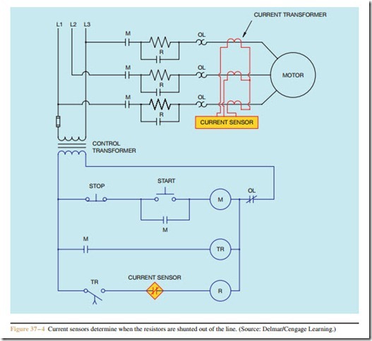
Another way of determining when to shunt the re- sistors out of the circuit is by sensing motor current. Current transformers are used to sense the amount of motor current (Figure 37 – 4). In this circuit, the current sensor contacts are normally closed. When the motor starts, high current causes the sensor contacts to open. An on-delay timer provides enough time delay to permit the motor to begin starting before contactor coil R can energize. This timer is generally set for a very short time delay. As the motor speed increases, the current
Step-Starting
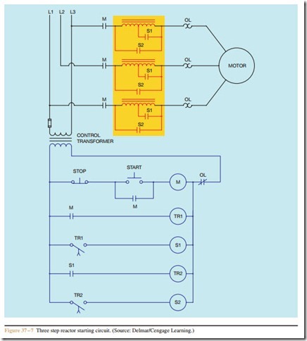
Some resistor and reactor starters use multiple steps of starting. This is accomplished by tapping the resistor or reactor to provide different values of resistance or inductive reactance (Figure 37 – 7). When the Start button is pressed, M load contacts close and connect the motor and inductors to the line. The M auxiliary contact closes and starts timer TR1. After a time delay, TR1 contact closes and energizes S1 coil. This causes half of the series inductors to be shunted out, reducing the inductive reactance connected in series with the motor. Motor current increases, causing the motor speed to increase. The S1 auxiliary contact closes at the same
time, causing timer TR2 to start its timing sequence. When TR2 contact closes, contactor S2 energizes, causing all of the inductance to be shunted out. The motor is now connected directly to the power line. Some circuits may use several steps of starting, de- pending on the circuit requirements.
1. What two electrical components are commonly connected in series with a motor to limit starting current?
2. What advantage does a reactor have when limiting in-rush current that is not available with a resistor?
3. Refer to the circuit shown in Figure 37 – 1. Assume that timer TR is set for a delay of 10 seconds. When the Start button is pressed, the motor starts in low speed. After a delay of 30 seconds, the motor is still in its lowest speed and has not accelerated to normal speed. Which of the following could not cause this condition?
a. The Start button is shorted.
b. Timer coil TR is open.
c. Contactor coil R is open.
d. Timed contact TR did not close after a delay of 10 seconds.
4. Refer to the circuit shown in Figure 37 – 7. Assume that each timer is set for a delay of 5 seconds. When the Start button is pressed, the motor starts
at its lowest speed. After a delay of 5 seconds, the motor accelerates to second speed. After another delay of 5 seconds, the motor stops running. During troubleshooting you discover that the control transformer fuse is blown. Which of the following could cause this condition?
a. TR1 coil is shorted.
b. S1 coil is open.
c. S2 coil is shorted.
d. TR2 coil is open.
5. Refer to the circuit shown in Figure 37 – 7. Assume that each timer is set for a delay of 5 seconds. When the Start button is pressed, the motor starts at its highest speed. Which of the following could cause this condition?
a. The Stop button is shorted.
b. TR1 timer coil is open.
c. S1 auxiliary contact is shorted.
d. TR2 timer coil is shorted.
