Characteristics of D.C. Generators
Following are the three most important characteristics or curves of a d.c. generator :
1. No-load saturation Characteristic (E0/If)
It is also known as Magnetic Characteristic or Open-circuit Characteristic (O.C.C.). It shows the relation between the no-load generated e.m.f. in armature, E0 and the field or exciting current If at a given fixed speed. It is just the magnetisation curve for the material of the electromagnets. Its shape is practically the same for all generators whether separately-excited or self-excited.
2. Internal or Total Characteristic (E/Ia)
It gives the relation between the e.m.f. E actually induces in the armature (after allowing for the
demagnetising effect of armature reaction) and the armature current Ia. This characteristic is of interest mainly to the designer and can be obtained as explained in Art. 28.12.
3. External Characteristic (V/I)
It is also referred to as performance characteristic or sometimes voltage-regulating curve.
It gives relation between that terminal voltage V and the load current I. This curve lies below the internal characteristic because it takes into account the voltage drop over the armature circuit resistance. The values of V are obtained by subtracting IaRa from corresponding values of E. This characteristic is of great importance in judging the suitability of a generator for a particular purpose. It may be obtained in two ways (i) by making simultaneous measurements with a suitable voltmeter and an ammeter on a loaded generator (Art. 28.10) or (ii) graphically from the O.C.C. provided the armature and field resistances are known and also if the demagnetising effect (under rated load con- ditions) or the armature reaction (from the short-circuit test) is known.
Separately-excited Generator
(a) (i) No-load Saturation Characteristic (E0/If)
The arrangement for obtaining the necessary data to plot this curve is shown in Fig. 28.1. The exciting or field current If is obtained from an external independent d.c. source. It can be varied from zero upwards by a potentiometer and its value read by an ammeter A connected in the field circuit as shown.
Hence, if speed is constant, the above relation becomes E = kF It is obvious that when If is increased from its initial small value, the flux F and hence generated e.m.f. Eg increase directly as current so long as the poles are unsaturated. This is represented by the straight portion Od in Fig. 28.1 (b). But as the flux density increases, the poles become saturated, so a greater increase in If is required to produce a given increase in voltage than on the lower part of the curve. That is why the upper portion db of the curve Odb bends over as shown.
(ii) Load Saturation Curve (V/If)
The curve showing relation between the terminal voltage V and field current If when the genera- tor is loaded, is known as Load Saturation Curve.
The curve can be deduced from the no-load saturation curve provided the values of armature reaction and armature resistance are known. While considering this curve, account is taken of the
demagnetising effect of armature reaction and the voltage drop in armature which are practically absent under no-load conditions. The no-load saturation curve of Fig. 28.1 has been repeated in Fig.
28.2 on a base of field amp-turns (and not current) and it is seen that at no-load, the field amp-turns required for rated no-load voltage are given by Oa. Under load conditions, the voltage will decrease due to demagnetising effect of armature reaction. This decrease can be made up by suitably increasing the field amp-turns. Let ac represent the equivalent demagnetising amp-turns per pole. Then, it means that in order to generate the same e.m.f. on load as at no-load, the field amp-turns/pole must be increased by an amount ac = bd. The point d lies on the curve LS which shows relation between the voltage E generated under load conditions and the field amp-turns. The curve LS is practically parallel to curve Ob. The terminal voltage V will be less than this generated voltage E by an amount = Ia Ra where Ra is the resistance of the armature circuit. From point d, a vertical line de = IaRa is drawn. The point e lies on the full-load saturation curve for the generator. Similarly, other points are obtained in the same manner and the full-load saturation curve Mp is drawn. The right-angled triangle bde is known as drop reaction triangle. Load saturation curve for half-load can be obtained by joining the mid-points of such lines as mn and bd etc. In the case of self-excited generators, load saturation curves are obtained in a similar way.
(b) Internal and External Characteristics
Let us consider a separately-excited generator giving its rated no-load voltage of E0 for a certain constant field current. If there were no armature reaction and armature voltage drop, then this voltage would have remained constant as shown in Fig. 28.3. by the dotted horizontal line I. But when the generator is loaded, the voltage falls due to these two causes, thereby giving slightly dropping characteristics. If we subtract from E0 the values of voltage drops due to armature reaction for different loads, then we get the value of E–the e.m.f. actually induced in the armature under load conditions. Curve II is plotted in this way and is known as the internal characteristic. The straight line Oa represents the IaRadrops corresponding to different armature currents. If we subtract from E the armature drop IaRa, we get terminal voltage V. Curve III represents the external characteristic and is obtained by subtracting ordinates the line Oa from those of curve II.
No-load Curve for Self-excited Generator
The O.C.C. or no-load saturated curves forself-ex cited generators whether shunt or seriesconnected, are obtained in a similar way.
The field winding of the generator (whether shunt or series wound) is disconnected from the machine and connected to an external source of direct current as shown in Fig. 28.4. The field or exciting current If is varied rheostatically and its value read on the ammeter A. The machine is drived at constant speed by the prime mover and the generated e.m.f. on on-load is measured by the voltmeter connected across the ar- mature. If is increased by suitable steps (starting from zero) and the corresponding values of E0 are mea- sured. On plotting the relation between If and E0, a curve of this form shown in Fig. 28.5 is obtained.
Due to residual magnetism in the poles, some e.m.f. (= OA) is generated even when If = 0. Hence, the curve starts a little way up. The slight curvature at the lower end is due to magnetic inertia. It is seen that the first part of the curve is practically straight. This is due to the fact that at low flux densities, reluctance of iron path being negligible (due to high permeability), total reluctance is given by the air- gap reluctance which is constant. Hence, the flux and consequently, the generated e.m.f. is directly
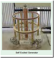
Self Excited Generator
proportional to the exciting current. However, at high flux densities, – where µ is small, iron path reluctance becomes appreciable and straight relation between E and If no longer holds good. In other words, after point B, saturation of poles starts. However, the initial slope of the curve is determined by air-gap width.
It should be noted that O.C.C. for a higher speed would lie above this curve and for a lower speed, would lie below it.
It should also be noted and the load-saturation curve for a shunt generator is similar to the one shown in Fig. 28.2.
Critical Resistance for Shunt Generator
Now, connect the field windings back to the armature and run the machine as a shunt generator. Due to residual magnetism in the poles, some e.m.f. and hence current, would be generated. This current while passing through the field coils will strengthen the magnetism of the poles (provided field coils are properly connected as regards polarity). This will increase the pole flux which will further increase the generated e.m.f. Increased e.m.f. means more current which further increases the flux and so on. This mutual reinforcement of e.m.f. and flux proceeds on till equilibrium is reached at some point like P (Fig. 28.6). The point lies on the resistance line OA of the field winding. Let R be the resistance of the field winding. Line OA is drawn such that its slope equals the field winding resistance i.e. every point on this curve is such that volt/ampere = R.
The voltage OL corresponding to point P represents the maximum voltage to which the machine will build up with R as field resistance. OB represents smaller resistance and the corresponding voltage OM is slightly greater than OL. If field resistance is increased, then slope of the resistance line increased, and hence the maximum voltage to which the generator will build up at a given speed, decreases. If R is increased so much that the re- sistance line does not cut the O.C.C. at all (like OT ), then obviously the machine will fail to excite i.e. there will be no ‘build up’ of the voltage. If the resistance line just lies along the slope, then with that value of field resistance, the machine will just excite. The value of the resistance represented by the tangent to the curve, is known as critical resistance Rc for a given speed.
How to Find Critical Resistance R ?
First, O.C.C. is plotted from the given data. Then, tangent is drawn to its initial portion. The slope of this curve gives the critical resistance for the speed at which the data was obtained.
How to Draw O.C.C. at Different Speeds ?
Suppose we are given the data for O.C.C. of a generator run at a fixed speed, say, N1. It will be shown that O.C.C. at any other constant speed N2 can be deduced from the O.C.C. for N1. In Fig. 28.7 the O.C.C. for speed N1 is shown.
Critical Speed Nc
Critical speed of a shunt generator is that speed for which the given shunt field resistance represents critical resistance. In Fig. 28.8, curve 2 corresponds to critical speed because Rsh line is tangen- tial to it. Obviously
For this generator find (i) no load e.m.f. for a total shunt field resistance of 100 W (ii) the critical field resistance at 1500 r.p.m. and (iii) the magnetization curve at 1200 r.p.m. and therefrom the open-circuit voltage for a field resistance of 100 W.
(b) A long shunt, compound generator fitted with interpoles is cummutatively-compounded. With the supply terminals unchanged, the machine is now run as compound motor. Is the motor differentially or cumulatively compounded ? Explain. (Elect, Machines, A.M.I.E. Sec. B, 1990)
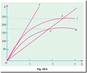
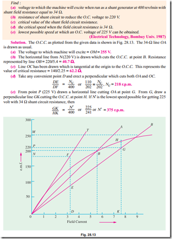
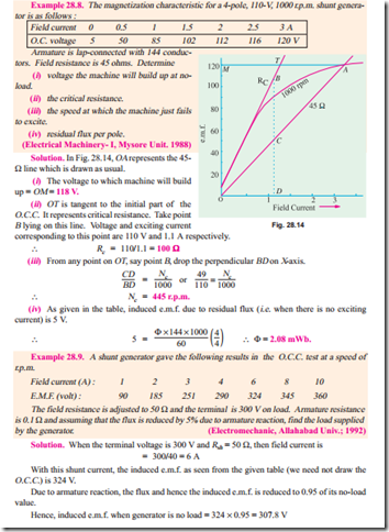
Solution. The magnetisation curve at 1500 r.p.m. is plotted in Fig. 28.9 from the given data. The 100 W resistance line OA is obtained by joining the origin (0, 0) with the point (1A, 100 V).
The voltage corresponding to point A is 227.5 V. Hence, no-load volt-age to which the generator will build-up is 227.5 V.
The tangent OT represents the critical resistance at 1500 r.p.m. considering point B, Rc = 225/1.5 = 150 W.
For 1200 r.p.m., the induced voltages for different field currents would be (1200/1500) = 0.8 ofthose for 1500 r.p.m. The values of these voltages are tabulated be- low :
The new magnetisation curve is also plotted in Fig. 28.9. The 100 W line cuts the curve at point C which corresponds to an induced voltage of 166 V.
Example 28.2. A shunt generator is to be converted into a level compounded generator by the addition of a series field winding. From a test on the machine with shunt excitation only, it is found that the shunt current is 3.1 A to give 400 V on no load and 4.8 A to give the same voltage when the machine is supplying its full load of 200 A. The shunt winding has 1200 turns per pole. Find the number of series turns required per pole. (Elect. Machines, A.M.I.E. Sec. B, 1989)
Solution. At no-load the ampere turns required to produce 400 V = 3.1 ´ 1200 = 3720 On full-load ampere turns required to produce the same voltage = 4.8 ´ 1200 = 5760 Additional ampere turns required due to de-magnetising effect of load current = 5760 – 3720 = 2040.
If N is a number of series turns required when load current is 200 A, then N ´ 200 = 2040, N = 10.2 Example 28.3. The open-circuit characteristic of a d.c. shunt generator driven at rated speed is as follows :
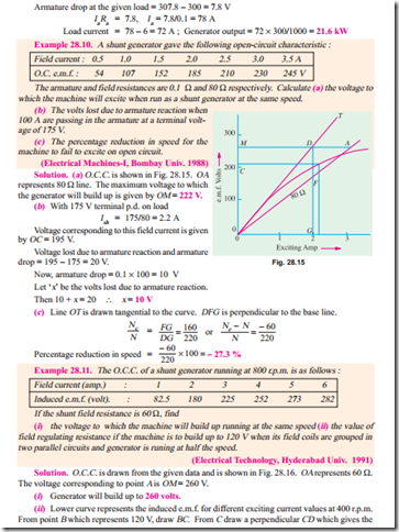
exciting current of 3.6 A. It means that current through each parallel path of shunt field coils is 3.6 A. Total current which passes through the field regulator resistance is 3.6 ´ 2 = 7.2 A because it is in series with the field coils.
Hence, total shunt field resistance = 120/7.2 = 16.67 W
Now, resistance of each shunt parallel path = 60/2 = 30 W
Joint resistance of two parallel paths = 30/2 = 15 W
Shunt field regulator resistance = 16.67 – 15 = 1.67 W
Related posts:
Incoming search terms:
- DC generators
- characteristics of dc generator
- dc generator characteristics
- characteristic of dc generator
- experiment load(external)charactristic of D C separately excited generator
- generator characterstics
- dc generator saturation curve
- no load characteristics of dc generator
- the reason behind the addition or subtraction of flux in series or shunt generator
- Load characteristics of dc generator
- no load saturation characteristics of dc generator
- external characteristics of dc generator at no load
- Determination of Characteristic Curves of a Compound Generator
- distinguish between external and internal characteristics of a dc generator
- external characteristics of series generator at no load
- self-excited dc generator characteristic
- critical speed of dc generator
- dc electromagnetic generator characteristics
- open circuit characteristic of dc shunt generator at rpm
- Problems on open circuit characteristics
- charterstics of dc
- What is reason behind gap in internal characteristics and external characteristics of dc compound generator
- external characteristics of dc generator
- problem on occ to find open circuit voltage and critical resistance by using graph
- explain the load saturation curve of dc generator
- characteristics of a generator
- problems on the open circuit characteristics of the DC generator
- why the occ for decreasing value of feild current lies slightly above than that of the increasing feild current
- To plot the o c c of a d c generator & find the critical resistance
- dc series generator characteristics
- occ curve
- characteristics and principles of a Direct Current (DC) generator
- the slight curvature at the lower end of the occ of a self excited dc generator is due to
- operating characteristics of dc generators
- purpose of drawing of external characteristics of dc generator
- how the o c c should be plotted
- d c generator characterist
- draww occ and finf speed field resistamce graphically
- Finding V line shunt generators
- the slight curvature at the lower end of the OCC of the self excited generator is due to
- occ curve explanation
- charactristics of machines two name
- why the occ for decreasing value of field current lies slightly above than that of the increasing field current
- characteristics of separately excited dc generator
- why the terminal voltage of a separately excited dc generator falls as it is loaded
- load saturation characteristics of a dc generator gives relation between
- explain characteristics of dc generator
- critical field resistance of dc shunt generator
- field resistance and emf occ curve
- what is meant by internal characteristics of d c generator


