SHAFT SEALS AND SEAL OIL SYSTEMS
The seals are located in the end shields. They seal the hydrogen in the machine where the rotor shaft emerges from the casing and shields. The main types of seals are thrust and journal seals.
Thrust-Type Seal
Figure 13.14 illustrates a thrust-type seal. The seal ring acts as a thrust face acting on a shaft collar. Oil is supplied to a central circumferential groove in the white-metal face of the seal ring. The oil pressure is higher than the casing hydrogen. Most of the oil flows outward due to centrifugal forces over the thrust face. It then drains into a well. A small oil flow moves inward against centrifugal forces. This flow is driven by the difference between the oil and the hydrogen into a drainage compartment, which is at hydrogen pres- sure. Entrained air and water can be released from this oil, resulting in contamination of the hydrogen. Therefore, it is important to minimize this oil flow.
The housing of the seal ring must be able to move axially about 30 mm to accommodate the thermal expansion of all the coupled rotors. The housing is designed to move inside a stationary member. It uses rubber sealing rings to contain the oil and exert axial pressure at the seal face.
Some seal designs have an additional chamber between the fixed and sliding compo- nents. It is fed with oil at varying pressures to control the overall pressure at the seal face. Other seal designs have additional pressure provided by springs.
Journal-Type Seal
This seal design is similar to a journal bearing floating on the shaft. This design allows the shaft to move axially through the seal. Thus, it does not need to accommodate the thermal expansion of the shaft. Again, oil is supplied to an annular groove in the white-metal ring. It flows in the clearances between the shaft and the bore of the seal. The flow is outward to a drain and inward to the space pressurized by hydrogen. The inward flow rate is much larger than the inward flow rate in the thrust-type seal because it is not inhibited by centrifugal forces. Thus, this flow is capable of contaminating the hydrogen significantly. The oil fed to the seals is subjected to vacuum treatment to reduce the contamination level of the hydrogen. The treatment involves the removal of air and water from the oil. Despite this disadvantage, the journal-type seal is considered better able to handle the axial movement of the shaft.
A more sophisticated design of the journal-type seal involves two separate oil supplies (Fig. 13.15). They are for the inward and outward flows. This design eliminates the need for vacuum treatment. The oil supplied is different from the turbine lubricating oil supply, which is the main source of entrained water.
GENERATOR COMPONENTS, AUXILIARIES, AND EXCITATION 13.37
Seal Oil System
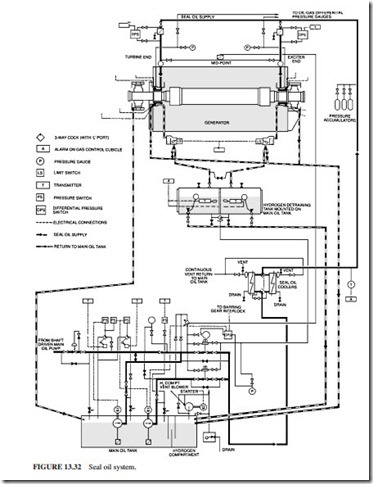
In conventional design (Fig. 13.32), the shaft-driven lubricating oil pump supplies the oil for the main seal. The oil pressure is controlled by a diaphragm valve, which main- tains a constant differential pressure above the hydrogen pressure at the seals. A water- cooled heat exchanger is used to cool the oil. The oil is sent through a fine filter to
prevent metallic particles from reaching the tight clearances in the seal. When the unit is shut down, motor-driven pumps are used to supply the seals with oil. They are used as emergency backup. They are initiated by the dropping pressure of the seal oil. They are normally vertical submerged pumps mounted on top of the lubricating oil tank. A dc pump is also provided in case of emergencies (loss of ac power). This pump is expected to operate for a few hours only, while the hydrogen is scavenged. There is a possibility that hydrogen will enter the drain tank. Low-level alarms are normally installed. A blower is used to exhaust the gas above the oil in the tank to atmosphere. The blower reduces the pressure in the bearing housings by creating a vacuum in the tank to reduce the egress of oil vapor at the bearings.

