Test Procedure Example 3
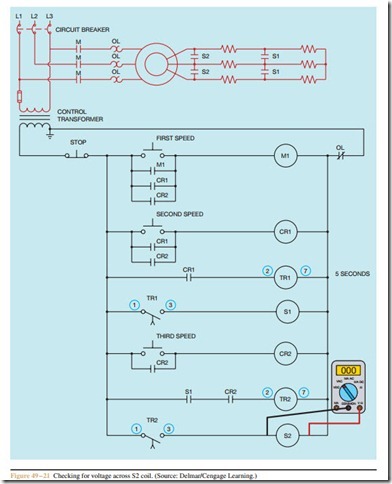
The next circuit to be discussed is shown in Figure 49 – 20. This circuit permits the motor to be started in any of three speeds with a 5 second time delay be- tween accelerating from one speed to another. Regard- less of which speed push button is pressed, the motor must start in its lowest speed and progress to the selected speed. It is assumed that eight-pin on-delay timers are used to provide the time delay for acceleration to the next speed.
Assume that when the THIRD SPEED push button is pressed, the motor starts in it lowest speed. After 5 seconds the motor accelerates to second speed but never increases to third speed. As in the previous examples, start by making a mental list of the conditions that could cause this problem:
1. Contactor S2 is defective.
2. Timed contact TR2 did not close.
3. Timer TR2 is defective.
4. CR2 or S1 contacts connected in series with timer TR2 did not close.
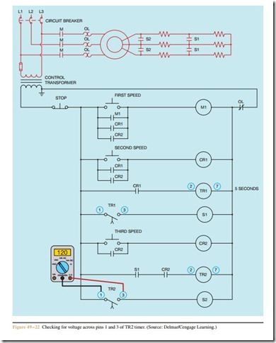
Begin troubleshooting this circuit by pressing the THIRD SPEED push button and permitting the motor to accelerate to second speed. Wait at least 5 sec- onds after the motor has reached third speed and connect a voltmeter across the coil of S2 contactor (Figure 49 – 21). Now, assume that the voltmeter indicated a reading of 0 volts. This indicates that there is no power being applied to the coil of S2 contactor. The next step is to check for voltage across pins 1 and 3 of timer TR2 (Figure 49 – 22). If the voltmeter indicates a value of 120 volts, it is an indication that the normally open timed contact has not closed.
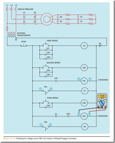
If timed contact TR2 has not closed, check for volt- age across timer TR2 (Figure 49 – 23). This can be done by checking for voltage across pins 2 and 7 of the timer. If a value of 120 volts is present, the timer is receiving power, but contact TR2 did not close. This is an indication that the timer is defective and should be replaced. If the voltage across timer coil TR2 is 0, then the volt- meter should be used to determine if contact CR2 or S1 is open.
Troubleshooting is a matter of progressing logically through a circuit. It is virtually impossible to troubleshoot a circuit without a working knowledge of schematics. You canít determine what a circuit is or is not doing if you donít understand what it is intended to do in normal operation. Good troubleshooting techniques take time and practice. As a generally rule, it is easier to progress backward though the circuit until the problem is identified. For example, in this circuit, contactor S2 provided the last step of acceleration for the motor. Starting at contactor S2 and progressing back- ward until determining what component was responsible for no power being applied to the coil of S2 was much simpler and faster than starting at the beginning of the circuit and each component.
Review Questions
1. What are the three main electrical test instruments used in troubleshooting?
2. What is the advantage of a plunger type voltage tester?
3. A motor is tripping out on overload. The motor nameplate reveals a full load current of 68 am- peres. When the motor is operating under load, an ammeter indicates the following: Phase #1 = 106 amperes, Phase #2 = 104 amperes, and Phase #3 = 105 amperes. What is the most likely problem with this motor?
4. A motor is tripping out on overload. The motor nameplate reveals a full load current of 168 am- peres. When the motor is operating under load, an ammeter indicates the following: Phase #1 = 166 amperes, Phase #2 = 164 amperes, and Phase #3 = 225 amperes. What is the most likely problem with this motor?
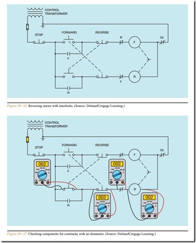
5. Refer to the circuit shown in Figure 49 – 16. The motor will not start in either the forward or re- verse direction when the start push buttons are pressed. Which of the following could not cause this problem?
a. F coil is open.
b. The overload contact is open.
c. The control transformer fuse is blown.
d. The STOP push button is not making a complete circuit.
6. Refer to the circuit shown in Figure 49 – 16.
Assume that the motor is running in the forward direction. When the REVERSE push button is pressed, the motor continues to run in the forward direction. Which of the following could cause this problem?
a. The normally open side of the REVERSE push button is not making a complete circuit when pressed.
b. R contactor coil is open.
c. The normally closed side of the REVERSE push button is not breaking the circuit when the REVERSE push button is pressed.
d. There is nothing wrong with the circuit. The STOP push button must be pressed before the motor will stop running in the forward direction and permit the motor to be reverse.
7. Refer to the circuit shown in Figure 49 – 20. When the THIRD SPEED push button is pressed, the motor starts in first speed but never accelerates to second or third speed. Which of the following could not cause this problem?
a. Control relay CR1 is defective.
b. Control relay CR2 is defective.
c. Timer TR1 is defective.
d. Contactor coil S1 is open.
8. Refer to the circuit shown in Figure 49 – 20.
Assume that the THIRD SPEED push button is pressed. The motor starts in it second speed, skipping first speed. After 5 seconds the motor accelerates to third speed. Which of the following could cause this problem?
a. S1 contactor coil is open.
b. CR1 contactor coil is open.
c. TR1 timer coil is open.
d. S1 load contacts are shorted.
9. Refer to the circuit shown in Figure 49 – 16. If a voltmeter is connected across the normally open FORWARD push button, the meter should indicate a voltage value of:
a. 0 volt
b. 30 volts
c. 60 volts
d. 120 volts
10. Refer to the circuit shown in Figure 49–20.
Assume that a fused jumper is connected across terminals 1 and 3 of TR2 timer. What would happen if the jumper were left in place and the FIRST SPEED push button pressed?
a. The motor would start in its lowest speed and progress to second speed, but never increase to third speed.
b. The motor would start operating immediately in third speed.
c. The motor would not start.
d. The motor would start in second speed and then increase to third speed.
