THYRISTOR CONTROL OF ARMATURE VOLTAGE AND CURRENT
As we saw in Chapter 4. an SCR can perform most of the duties of a rheostat in
controlhng the average current to a load. Furthermore, an SCR, or any power
thyristor, does not have the shortcomings of high-power rheostats. SCRs are small,
inexpensive, and energy-efficient. It is therefore natural to match the dc shunt
motor and the SCR to provide armature control of motor speed. The general layout
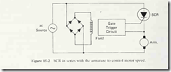
of an SCR speed control system is illustrated in Fig. 15-2.
In Fig. 15-2, the ac power is rectified to produce dc power for the field wmding.
The SCR then provides half-wave rectification and control to the armature winding.
By firing the SCR early, the average armature voltage and current are increased,
and the motor can run faster. By firing the SCR later {increasing the firing delay
angle), the average armature voltage and current are reduced, and the motor runs
slower. The gate trigger control circuit can be either an open-loop circuit or a
closed-loop, automatically correcting circuit.
Of course. Fig. 15-2 is not the only arrangement of an armature with an SCR
that is acceptable. Either of the circuits shown in Fig. 4-11 or 4-13(b) will also
work, with the motor armature being the circuit’s load. The circuits of Figs. 4-11
and 4- 13(b) may even be preferable to the circuit in Fig. 15-2 because they provide
full-wave power control instead of half-wave control.
SINGLE-PHASE HALF-WAVE SPEED CONTROL SYSTEM FOR A DC SHUNT MOTOR
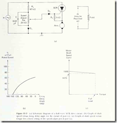
Figure 15-3 shows a simple half-wave speed control circuit for a dc motor. The
motor speed is adjusted by the 25-kO speed-adjust pot. As that pot is turned up
(wiper moved away from ground) the motor speed increases. This happens because
the gate voltage relative to ground becomes a greater portion of the ac line voltage
thus allowing the gate-to-cathode voltage to reach the firing vohage of the SCR
eariier in the cycle.
As the speed-adjust pot is moved downward, the gate-to-ground voltage
becomes a smaller portion of the line voltage, so it takes longer for V,^,^ to reach
the value necessary to fire the SCR.
The relationship between speed and firing delay angle for this system is
graphed in Fig. 15-3(b). As can be seen, it is impossible for the motor to attain
100% of its full rated speed because the system can deliver only half-wave power
to the armature.
This system has a desirable feature which tends to stabilize the motor speed
even in the face of load changes. The feature is called counter-EMFfeedback. Here
is how it works.
Suppose the speed-adjust pot is positioned to provide a shaft speed of 1500
rpm. If the torque load on the motor now increases, there is a natural tendency
for the motor to slow down. It does this so that the counter-EMF can decrease
slightly, thus allowing an increased armature current to flow. The increased armature
current provides the boost in torque needed to drive the heavier load. This
is the natural reaction of all motors.
In the system of Fig. 15-3, though, when the counter-EMF decreases, the
cathode-to-ground voltage (V^^) decreases, since V^- depends in large part on the
counter-EMF generated by the armature winding. If Vf; decreases, the firing of the
SCR takes place earlier because V^; does not have to climb as high as before to
make V^-^ large enough to fire the SCR. Therefore, an increase in torque load
automatically produces a reduction in firing delay angle and a consequent increase
in average armature voltage and current. This action holds the motor speed almost
constant, even in the face of varying torque load. The graph of motor speed versus
load torque is presented in Fig. 15-3(c), assuming an initial no-load shaft speed of
150U rpm.
The ability of a speed control system to maintain fairly constant motor speed
in the face of varying load is called its load regulation. In formula form, the load
regulation is given as
where RPM^i stands for the rotational speed at no load. The phrase no load means
that the load countertorque tending to slow down the motor shaft equals zero.
RPMp, stands for the rotational speed at full load, meaning that the load countertorque
tending to slow down the motor shaft is at maximum. It can be seen
from Eq. (15-4) that the smaller the change in speed from the no-load condition
to the full-load condition, the smaller the load regulation. Therefore, the smaller
the load regulation figure, the better the control system.
The drive system of Fig. 15-3 provides good load regulation. This is another
advantage over the speed control methods described in Sec. 15-1.
As a specific example of calculating load regulation, refer to Fig. 15-3(c). We
can see that the no-load speed is 1500 rpm and that the full-load speed is 1475
rpm. Therefore, the load regulation is given by
For many industrial applications, a load regulation of 1.7%’ is quite adequate

