STROMBERG WW OVERHAUL
Carburetor Disassemble
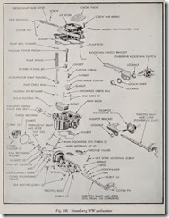
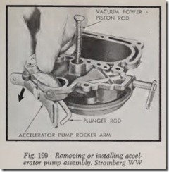
Air Horn-Remove the fast idle rod and pump operating rod. Remove all air horn attaching screws and carefully lift off vertically the air horn assembly. Disengage the pump plunger rod by tilting slightly and remove pump plunger, Figs. 198 and 199.
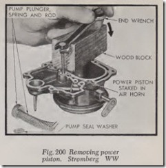
To remove the vacuum power piston, use an open end wrench and a wood block as shown in Fig. 200. Use care as pressure is applied as the assembly is staked in position. The choke plate and shaft can be removed if necessary. Care should be exercised when removing screws to prevent breaking them off in the shaft.
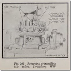
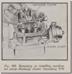
Main Body-Remove idle tubes as shown in Fig. 201. Invert carburetor and remove accelerator pump inlet check ball. Do not remove the two dome-shaped high speed bleed ers in the main discharge strut of the main body. Remove acceler ator pump discharge cluster and invert the body to allow the accelerator pump discharge check ball to drop out, Fig. 202.
Remove float inlet needle and seat. Inspect for grooving. Use a small screwdriver to pry out the float fulcrum retaining spring. Cover the float chamber to pr event spring flying out. Then lift out float.
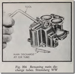
Remove power by-pass jet and gasket, Fig. 203. Test plunger action of by-pass jet. Invert main body and remove main metering jet plugs. A special tool is needed to remove main metering jets (see Fig. 146). Then use the tool shown in Fig. 204 to remove the main discharge jets or tubes. As shown in Fig. 207, this tool has a tapered right-hand thread and should be screwed into the jet. The threads formed by the tool will not damage the jets.
The main body is attached to the throttle body by four screws in the bottom of the throttle body. If separated, always use a new gasket.
Throttle Body-A new throttle shaft can be installed but if clearance between shaft and bore is excessive enough to cause poor idling, the as sembly should be replaced.
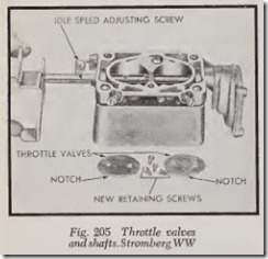
To remove the shaft, first remove the lock nut located in the choke housing. Then remove the throttle valve retaining screws. These should be removed with care to prevent screws being broken in the shaft. Mark the valves so they are installed in the correct bores, Fig. 205. When valves are installed, make sure that the small notch in the valve is toward the idle port.
Carburetor Assemble
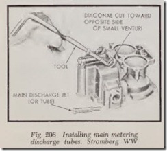
Assemble throttle body to main body using a new gasket. Place main discharge jets on the tool shown in Fig. 206 and install into position. Make sure the opening in end of tube (diagonal cut end) is facing opposite side of small venturi. Insert main metering jets over discharge jets and tighten. Then install gasket and plug. Install power by-pass jet and gasket.
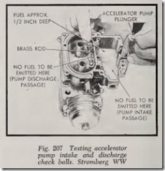
Testing Accelerator Pump-Install the acceler ator pump inlet check ball ( 3/16″ diameter) in check ball seat at the bottom of the pump cylin der. Install the accelerating pump discharge check ball ( {{‘ diameter) in the orifice in the center passage of the discharge strut section of the main body.
Pour clean gasoline into the carburetor bowl, approximately deep. Raise the plunger and press lightly on the plunger shaft to expel the air from the pump passage. Using a small, clean brass rod, hold the discharge check ball firmly down on its seat, Fig. 207. Again raise the plunger and press downward. No fuel shoult;l be ejected from either the intake or discharge passages. Install the discharge cluster gasket, cluster and screw. Tighten securely.
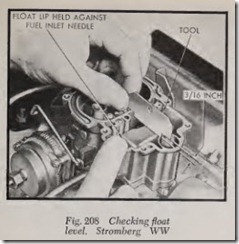
Float Level-Check the float for leaks or dam age. If satisfactory for further service, install in position in carburetor bowl. Assemble fuel inlet needle valve, seat and gasket, then inse1t in posi tion in main body. Tighten securely. Install float fulcrum pin retaining spring and force under lip of boss to keep fulcrum pin in position.
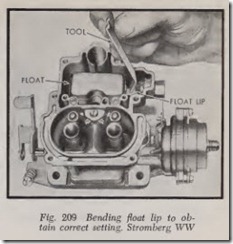
Using a “T” scale or the tool shown in Fig. 208, check the float setting. The top of the float must be 3/16″ from the top of the main body (gasket removed) with the gauge at the center of the flat and the float lip held firmly against the fuel inlet needle. To change the float setting, bend the float lip toward the needle to lower, and away from the needle to raise the float, Fig. 209.
Main Body Assemble-Install idle tubes in main body. Install vacuum power piston and plunger in air horn. Lock in position by prick punching on the retaining rim. Compress the piston plunger to be sure no binding exists. If the piston sticks or binds enough to hinder smooth operation, install a new piston assembly.
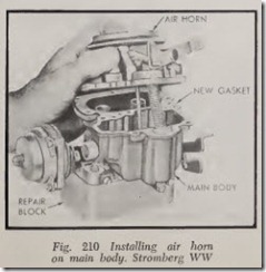
Slide a new air horn gasket over the accelerator pump plunger and down against the air horn. Lower the air horn slightly down on the main body with the accelerator pump plunger sliding into its well, Fig. 210. Be sure plunger leather does not fold or curl back. Install air horn retain ing screws and lock washers and tighten securely. Work the pump plunger several times to be sure it operates freely.
Adjustments
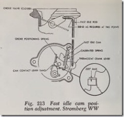
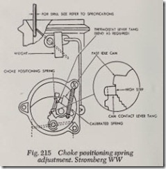
In making some of these adjustments, a special calibrated coil spring (Stromberg Tool No. T-25906) is essential. This calibrated spring is shown installed in Figs. 213, 215 and 217.
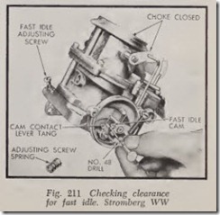
Fast Idle-To make this adjustment, remove the thermostat coil housing and install the special calibrated spring with a thermostat cover screw at one end and hook the other end to the long tang of the thermostat lever. Remove the spring from the fast idle adjusting screw, Fig. 211, and rein stall the screw without the spring.
With the throttle valves fully closed, turn the fast idle screw in so it just contacts the throttle lever. Then turn the adjusting screw in turns for 8-cylinder carburetors or 5 turns for 6-cylin der carburetors. This will open the throttle valves a predetermined amount.
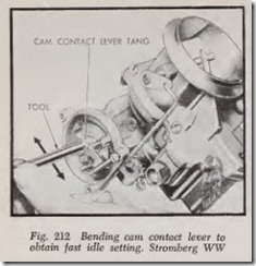
With the choke valve closed and the throttle level held against the fast idle screw, insert the proper size drill between the tang on the contact lever and the first step of the fast idle cam, Fig.
211. To adjust, slide the tool shown in Fig. 212 over tang on cam contact lever. Bend tang away from or toward fast idle cam until correct clear ance has been obtained. After adjusting, make sure the tang is parallel to the throttle shaft. Remove the fast idle speed adjusting screw and install the spring.
Fast Idle Cam-To position the fast idle cam, open the throttle valves sufficiently to clear the fast idle cam. Close the choke valve tightly by applying pressure on the choke valve. Now, force the throttle valves closed against the tension of the cam positioning spring as shown in Fig. 213. In this position, the tang on the cam contact lever should just clear the high step of the fast idle cam, Fig. 213. The clearance should not exceed .020″. Adjust, if necessary, by bending the fast idle rod (at angle) until the correct clearance has been obtained, Fig. 214.
Choke Positioning Spring-To make this adjust ment, slide the special weight tool shown in Fig.215 over the choke lever. Hold carburetor in a vertical position. Close throttle valves, making certain the cam contact lever tang is resting on the high step of the fast idle cam (it may be necessary to rotate the fast idle cam to obtain this adjust ment). Now, lightly close the throttle valves. The choke valve should open just enough to insert the proper drill between choke valve and wall of air horn, Fig. 215.
To adjust, bend the tang of the thermostat lever that contacts the choke positioning spring, using long nose pliers as shown in Fig. 216. After ad justment has been made, remove weight from choke lever.
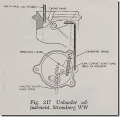
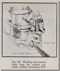
Unloader Adjustment- To make this adjust ment, lightly hold the choke valve closed, then open the throttle valves wide. The choke valve should open sufficiently to allow the proper size drill to be inserted between the choke valve and wall of air horn, Fig. 217. To adjust, bend the tang of the cam contact lever with long nose pliers, Fig. 218.
Remove the special calibrated spring and screw, then install the thermostat coil housing and gasket, being sure to align index marks.
Hold the choke open and then open and close the throttle valves. Failure to obtain full throttle operation indicates improper assembly or adjust ment of the choke mechanism. With the throttle valves held in open position, open the choke valve slowly to wide open position. There should be no bind throughout the entire travel of the choke mechanism.
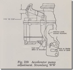
Accelerator Pump-The following adjustment is made with the accelerator pump rod in the center hole of the throttle lever. To check the pump travel, hold the carburetor in a vertical position. Then operate the pump to permit the check ball at the bottom of the well to take its normal position on the seat. With the choke valve held open, measure the travel of the pump as the throttle valves are moved from open to fully closed posi tion. The pump travel should measure 3/16″ to 7/32″ on 6-cylinder cars, Fig. 219.
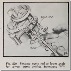
To adjust, remove the pump rod from the cen ter hole of the throttle lever and bend it at the angle as shown in Fig. 220 up or down until correct travel has been obtained. Reinstall rod.
Dashpot-With the idle speed adjusting screw set for normal idle speed, there should be 1/16″ to 3/32″ clearance between the end of the dashpot plunger on the throttle lever when the plunger is pushed to the end of its tr avel. To adjust, loosen the locknut and turn the dashpot in the bracket to obtain correct clearance.
Kickdown Switch-With the throttle valves wide open, there should be 1/64″ to 1/32″ clear ance between ear on throttle lever and the threaded portion of the switch housing. To adjust, loosen the adjusting lock nuts (see Fig. 198) and move the switch in or out until correct clearance has been obtained.
![Fig.-203-Removing-or-installing_thum[1] Fig.-203-Removing-or-installing_thum[1]](http://machineryequipmentonline.com/electric-equipment/wp-content/uploads/2020/07/Fig.-203-Removing-or-installing_thum1_thumb.jpg)
![Fig.-214-Bending-fast-idle-rod-to-ob[1] Fig.-214-Bending-fast-idle-rod-to-ob[1]](http://machineryequipmentonline.com/electric-equipment/wp-content/uploads/2020/07/Fig.-214-Bending-fast-idle-rod-to-ob1_thumb.jpg)
![Fig.-216-Bending-thermostat-lever_th[1] Fig.-216-Bending-thermostat-lever_th[1]](http://machineryequipmentonline.com/electric-equipment/wp-content/uploads/2020/07/Fig.-216-Bending-thermostat-lever_th1_thumb.jpg)
