Fabricating Cable Tray on Site
It is sometimes necessary to fabricate joints to meet particular installation requirements, or where a factory made accessory is not readily available.
Cable tray can be cut quite easily with a hacksaw. Careful measurement and marking out is required to obtain a satisfactory fit. Care should be taken to remove any sharp edges or burrs where the cable tray was cut.
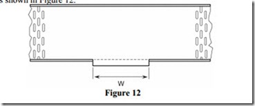
Mark the position of the Tee on the through section of tray. W is the width of the Tee section of tray. Ensure that this measurement is accurate by measuring the width of the tee section. Remember that the tee section may be a different size than the through section. Cut the flange and fold out as shown in Figure 12.
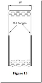
Cut away or fold out both flanges on Tee section of tray. Deburr all cut edges and “round off”
all corners as shown in Figure 13.
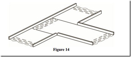
Drill holes as required to secure both pieces together with 6 mm galvanised round head bolts. Ensure that the heads of the bolts are inside the tray to prevent damage to any cable being installed. Tighten all bolts securely. See Figure 14
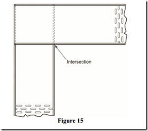
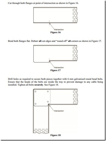
Place two pieces of tray so that they overlap each other. Mark point of intersection as shown in Figure 15.
Cut through both flanges at point of intersection as shown in Figure 16.
Fabricating a Flat 90° Bend with Gusset
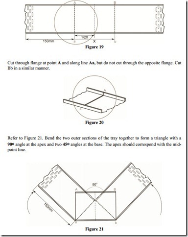
· Refer to Figure 19, measure and mark line Aa ( e.g. 150 mm ).
· Calculate dimension X = Ö2 ( W ) X = 1.414 x 100 = 141 mm.
· Mark the mid-point 1/2X.
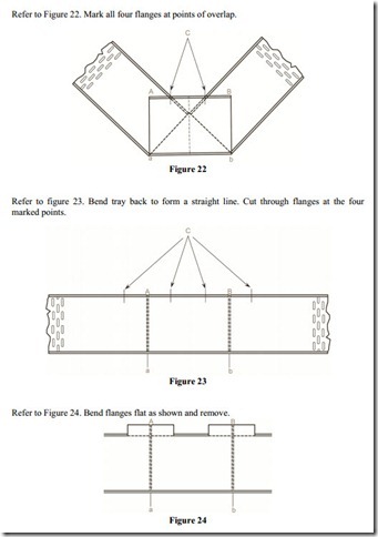
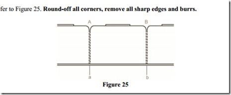
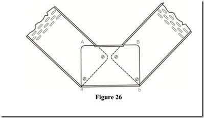
Bend tray to final position. Mark and drill holes as required to secure both pieces together with 6 mm galvanised round head bolts. Ensure that the heads of the bolts are inside the tray to prevent damage to any cable being installed. Tighten all bolts securely. See Figure 26.
External Bend
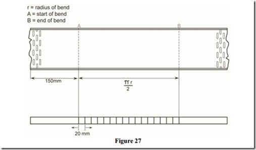
An external bend can be made to the required radius and in the correct position on a run of cable tray. It is not necessary to make an external bend and fix in the correct position. Mark the tray as per the example shown in Figure 27. The distance between lines A and B is the length of tray required to form a uniform bend of radius r. Mark the flanges at equal distances of approximately 20 mm between A and B.
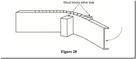
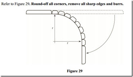
Cut through both flanges at the points marked. Bend the tray a small amount at each saw-cut. Continue bending at each saw-cut in turn until a uniform bend is achieved. The radius of the bend will automatically be correct.
Internal Bend
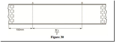
An internal bend can be made to the required radius and in the correct position on a run of cable tray. It is not necessary to make an internal bend and fix in the correct position. Mark the tray as per the example shown in Figure 30. The distance between lines A and B is the length of tray required to form a uniform bend of radius r.
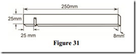
Figure 31 shows a simple tool for forming an internal bend in cable tray. It may be easily fabricated from a piece of mild steel. The groove which is cut in the left hand side, should be slightly wider than the flange of the cable tray. Alternately, an adjustable spanner may be used.
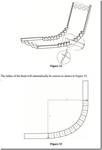
Bend both flanges, a small equal amount at a time as shown in Figure 32. Do not overbend. Let the width of the tool decide the distance between the bends. Continue bending over the distance AB. If a 90° bend is not achieved, simply bend slightly more at each point to maintain a uniform radius.
Related posts:
Incoming search terms:
- cable tray cutting measurement
- cable tray fabrication calculation
- cable tray bend calculation
- cable tray 90 degree bend formula
- A B C of how to fabricate electric cable tray
- electrical cable tray cutting formula
- cable tray fabrication formula
- cable tray 45 degree bend formula
- cable tray offset formula pdf
- cable tray cutting formula
- cable tray 90 cutting
- cable tray bending formula
- cable tray offset formula
- tray bending formula
- cable tray 90 formula
- cable tray upset
- cable tray offset formula in hindi
- tray fitter formula
- cable trey formula
- Cable Trays mail
- FORMULA FOR CUTTING CABLE TRAY SUPPORT
- cable tray bend computation
- cable tray bending techniques
- cable tray calculation formula
- cable tray fabrication formula pdf
- off formula in cable tray
- cabletray formula
- how to make 90 degree cable tray in 150mm
- how to fabricate cable tray
- tray cutting formula
- cable tray offset calculations
- cable tray formula
- 300 cabel try 90 bend maraking mesurment
- 45% faormula cable try
- cable tray fabrication and measurements
- cable tray fabrication cutting measurement
- फिटिंग mail
- 300x100 tray 90 cutting measurements
- cable tray 600 90 digree formula
- bending cable tray calc
- cable tray 90 and 45 making
- cable tray 90 bend fabrication
- cable tray 90 bend formula
- cable tray 50mm how to 90 degree mesurment
- cable tray 45 making caliculation
- Cable tray 90
- cabble tray band
- cabale tray formula cutting in hindi
- cabal tray cuting formula
- bending radius calculation formula
