CHRYSLER NOx
Oxides of Nitrogen
The NOx system controls oxides of nitrogen emissions by allowing vacuum spark advance only in high gear (manual transmission), or above 30 mph (automatic transmission), and with the use of an increased overlap camshaft and a 185 degree F. coolant thermostat. Vacuum to the distributor is controlled by a solenoid vacuum valve mounted in the line between the carburetor vacuum port and the distributor. When the solenoid is energized the plunger shuts off vacuum to the distributor and vents it to the atmosphere. When it is de-energized the plunger opens allowing normal vacuum spark advance. There are two separate systems employed to control the solenoid vacuum valve, one f or ve hicles equipped with manual transmissions and the other for those having automatic transm issions.
Manual Transmission
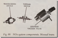
The NOx system for manual transmissions con sists of a solenoid vacuum valve, tran smission switch and in the 1971 system a thermal switch, Fig. 68. The solenoid vacuum valve is mounted and operates as explained above. The transm is sion switch is mounted on the transmission hous ing and is used to sense the transmis sion gear position. It remains closed (“on”) in any gear below high which energizes the solenoid thereby preventing vacuum spark advance. It opens when the top gear is selected permitting normal vacuum spark advance. The thermal switch is moun ted on the firewall and senses ambient air temperature. If the temperature is below 70 degrees F., this switch will be open. This breaks the circuit be-tween the transmission switch and the solenoid valve leaving the NOx system inoperative and al lowing normal vacuum spark advance in all gears.
Automatic Transmission
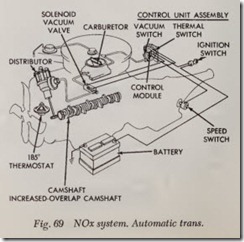
The NOx system for automatic transmission equipped vehicles consists of a solenoid vacuum valve, a speed switch and a control unit assembly, Fig. 69. The solenoid vacuum valve is mounted and operates as explained above. The speed switch senses the vehicle speed and is mounted in line with the speedometer cable. The conb·ol unit as sembly mounts on the fire wall. It contains three parts, the control module, the thermal switch and the vacuum switch. It senses ambient temperature and manifold vacuum. These components work together for one purpose, to prevent vacuum spark advance under following conditions:
1. Temperature above 70 degrees F.
2. Speeds below 30 mph.
3. Accel eration necessary on 1971 vehicles only. Whenever all conditions are present, the sole noid vacuum valve will be energized shutting off vacuum to the distributor.
CHRYSLER IGNITION
Electronic Ignition
A better control of exhaust emissions is achieved through the use of the “Electronic Ignition.” By eliminating the breaker points, engine misfiring and increased emissions caused by worn or mis adjusted breaker points is eliminated.
Distributor Solenoid, 1972-73
A start only solenoid is used on some distribu tors to provide additional spark advance during engine starting. The solenoid is located in the vacuum unit attached to the distributor housing and operates only while the ignition switch is in start position.
Use of the solenoid provides improved starting characteristics while maintaining a low level of hydrocarbon and carbon monoxide emissions at idle.
CHRYSLER ORIFICE SPARK ADVANCE CONTROL (OSAC)
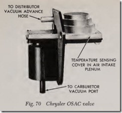
The OSAC system, Fig. 70, is used on all 1973- 77 engines, to aid in the control of NOx (Oxides of Nitrogen). The system controls the vacuum to the vacuum advance actuator of the distributor.
A tiny orifice is incorporated in the OSAC valve which delays the change in ported vacuum to the distributor by about 17 seconds when going from idle to part throttle. When going from part throt tle to idle, the change in ported vacuum to the distributor will be instantaneous. The valve will only delay the ported vacuum signal when the ambient temperature is about 60° F. or above. Vacuum is obtained by a vacuum tap just above the throttle plates of the carburetor. This type of tap provides no vacuum at idle, but provides manifold vacuum as soon as the throttle plates are opened slightly. Proper operation of this valve depends on air tight fittings and hoses and on free dom from sticking or plugging due to deposits.
TEMPERATURE OPERATED VACUUM
BY-PASS VALVE
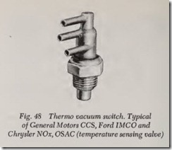
This vacuum by-pass or Thermal Ignition Con trol (TIC) valve, Fig. 48, is used on some engine applications to reduce the possibility of engine overheating under extremely high temperature operating conditions. When engine coolant tem perature at idle reaches 225° F., the valve opens automatically and applies manifold vacuum direct ly to the distributor for normal vacuum spark ad vance. This will by-pass the NOx or OSAC system. This increases engine idle speed and provides ad ditional engine cooling. When the engine has cooled to normal operating temperature, the NOx or OSAC system is restored to normal operation.
CHRYSLE.R EXHAUST GAS
RECIRCULATION (EGR)
In this system, exhaust gases are circulated to dilute the incoming fuel air mixture. Dilution of the incoming mixture lowers peak flame tempera tures during combustion and thus limits the for mation of NOx.
Floor Jet Exhaust Gas System 1972-73
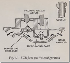
In this system the exhaust gases are introduced into the intake manifold through jets in the floor below the carburetor, Fig. 71. An orifice in each jet allows a controlled amount of exhaust gas to be drawn through by engine vacuum to dilute incoming fuel and air. In eight cylinder engines, exhaust gases are taken from the intake manifold exhaust crossover passage. while in six cylinder engines, gases are taken from the exhaust manifold “plenum” chamber located at the “hot spot” be low the carburetor riser.
NOTE: In 1973 two additional systems are used to control the rate of exhaust gas recirculation, depending on engine model. These systems are: Ported Vacuum Control System and Venturi Vac uum Control System.
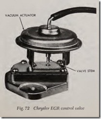
Both systems use the same type exhaust gas recirculation (EGR) control valve, Fig. 72, only the method of controlling the valve is different. The valve is a vacuum actuated, poppet type unit used to modulate exhaust gas How from the ex haust gas crossover into the incoming air fuel mix ture.
Venturi Vacuum Control System
The venturi vacuum control system utilizes a vacuum tap at the throat of the carburetor venturi to provide a control signal. This vacuum signal is amplified to the level required to operate the EGR control valve. Elimination of recycle at wide open throttle is accomplished by a dump diaphragm which compares venturi and manifold vacuum to determine when wide open throttle is achieved. At wide open throttle, the internal reservoir is “dumped,” limiting output to the EGR valve to manifold vacuum. The valve opening point is set above the manifold vacuums available at wide open throttle.
NOTE: This system is dependent primarily on engine intake airflow as indicated by the venturi signal, and is also affected by intake vacuum and exhaust gas back pressure.
Ported Vacuum Control System
The ported vacuum control system utilizes a slot type port in the carburetor throttle body which is exposed to an increasing ratio of manifold vacuum as the throttle blade opens. This throttle bore port is connected through an external nipple directly to the EGR valve. The How rate is dependent on three variables, 1) manifold vacuum, 2) throttle position, and 3) exhaust gas back pressure. Re cycle at wide open throttle is eliminated by cali brating the valve opening point above manifold vacuums available at wide open throttle as port vacuum cannot exceed manifold vacuum. Elimina tion of wide open throttle recycle provides maxi mum performance.
Temperature Control Valve
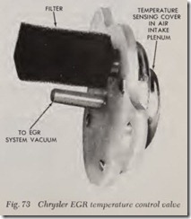
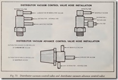
The plenum mounted temperature control valve, Fig. 73, is utilized on the ported vacuum control system and the venturi vacuum control system. The valve reduces the recycle rate at low ambient temperature for improved driveability. The unit contains a temperature sensitive bimetal disc which senses plenum air temperature. The snap action of the disc unplugs a calibrated orifice to provide the bleed air. Calibration is protected by an air filter unit.
Coolant Control Exhaust Gas Recirculation (CCE.GR)
1974-77 engines equipped with EGR use a CCEGR valve mounted in the radiator top tank, engine block or water pump housing. The purpose of this valve is to allow exhaust gas recirculation
only after the engine has reached a predetermined temperature.
Coolant Controlled Engine Vacuum Switch (CCEVS)
This switch is used on 1977 vehicles to improve hot driveability by preventing operation of the Idle Enrichment System, Power Heat Valve Sys tem and Air Injection Switching System after the coolant temperature has reached a predetermined temperature. When the engine coolant tempera ture is below 86° F. (green), 108° F. (orange) or 138° F. (neutral), the valve opens allowing mani fold vacuum to operate one or more of the systems previously mentioned.
EGR Delay System
Some 1974 vehicles are equipped with an EGR Delay System, which has an electrical timer mounted on the dash panel in the engine com partment controlling an engine mounted solenoid. This solenoid which is connected with vacuum hoses to the carburetor venturi and vacuum am plifier, prevents EGR operation for about 35 sec onds after engine start up.
EGR Time Delay & Idle Enrichment System
On most 1975-77 vehicles, a time delay device is used in the EGR system which works in con junction with the idle enrichment system to im prove engine starting and performance. This sys tem consists of an electronic timer and either one or two vacuum solenoids. The electronic timer energizes the solenoid ( s) during starting and for 35 seconds thereafter. When the solenoid ( s) en ergizes, vacuum to the EGR amplifier is cut off, thereby stopping exhaust gas recirculation. At the same time, vacuum is applied to the idle enrich ment system through the solenoid and/or a block coolant valve when the engine block temperature is below 98° F. for California vehicles or 150° F. for all other vehicles. On 1975-76 Calif. and all 1977 except U8-360, idle enrichment is controlled only by engine coolant temperature. The system used on V8-318 engines except California, func tions basically in the same manner except that it uses two vacuum solenoids, one controlling the EGR system, the other controlling the idle enrich ment system. Thirty-five seconds after engine start up, the solenoid ( s) de-energizes, allowing normal EGR operation and stopping idle enrichment.
EGR Maintenance Reminder System
This remin der system on 1975-77 vehicles uses a warning light in the instrumen t cluster, to alert the driver of the vehicle at 15,000 mile intervals to have the EGR system checked for the following:
1. Vacuum hose operation
2. EGR valve operation
3. CCEGR valve operation
4. Timer and solenoid operation
5. Intake manifold and EGR valve flow passages Once the EGR system has been properly serv iced, the reminder system must be reset for the next 15,000 mile interval and to turn off the warn ing light. If the EGR switch has to be replaced before a 15,000 mile interval, the EGR system maintenance check must be perform ed and the new switch installed.
FORD IMCO SYSTEM
Improved Exhaust Emission Control System
This system combines a thermostatically con trolled air cleaner and higher engine operating temperature with leaner carburetor calibration and later ignition timing under closed throttle operat ing conditions.
Dual Diaphragm Distributor
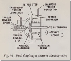
In addition to the conventional centrifugal and vacuum advance control units, the unit, Fig. 74, uses a separate diaphragm to retard the spark timing under closed throttle conditions. The ad vance diaphragm is connected to the carburetor above the throttle plate( s) so that when the throttle is opened, the timing is advanced. The retard diaphragm is connected to the intake mani fold so that during closed throttle operation, when manifold vacuum is high, the timing is retarded to provide more complete combustion.
Distributor Vacuum Control Valve
This valve, Fig, 75, is exposed to cooling system temperature and when coolant temperature ex ceeds normal limits during long idle periods, the valve opens a vacuum passage to the advance diaphragm of the distributor which speeds up the engine idle lowering the temperature.
Distributor Vacuum Advance Control Valve
This valve, Figs. 63 and 75, provides the neces sary ignition advance duri g acceleration periods to provide the most efficient combustion and re duce emissions.
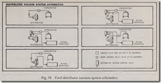
NOTE: Application of the distributor vacuum control valve and the dual-diaphragm vacuum advance mechanism will vary from vehicle to vehicle, Fig. 76.
FORD ELECTRONIC DISTRIBUTOR MODULATOR
Description
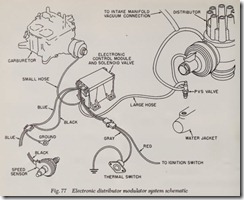
The system operates to prevent spark advance below 23 mph on acceleration and below approxi mately 18 mph on deceleration. Control by the modulator is canceled out if the outside air tem perature is below 58 deg. F., allowing the distributor to operate through the standard vacuum control system, Fig. 77.
The modular system consists of four com ponents: speed sensor, thermal switch, and elec trical control amplifier-solenoid valve. The control amplifier and solenoid valve are combined in one assembly and mounted in the passenger compart ment on the dash panel. The speed sensor is con nected to the speedometer cable. The thermal switch is mounted near the front door hinge pillar on the outside of the cowl panel. It may be mounted on either the right or left side.
