VOLTAGE SOURCES
To make current flow, we must have voltage. That voltage will produce either direct current (DC) or alternating current (AC). DC is electron flow in only one direction. AC is current that flows in one direction and then reverses and flows in the opposite direction.
DC Voltages
DC may be a fixed, steady current, one that varies, or one that switches off and on periodically. A DC voltage source is one that causes direct current to flow one way through the circuit, component, or conductor. It has positively and negatively charged terminals of a fixed polarity. It always causes electrons to flow from negative to positive.
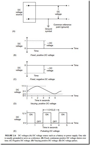
Figure 2.6A shows a fixed, positive DC voltage source, which is usually either a battery or an electronic power supply. We call it a positive source because the negative terminal of the DC source is connected to a common point called the ground. The other terminal is positive with respect to ground. Voltages are always looked at or measured between two points with one point (ground) being the reference. The polarity of the voltage is the polarity of the terminal not connected to ground.
The remainder of Figure 2.6 shows graphs of DC voltage over time. In electronics we normally view DC or AC voltages with respect to time. The positive DC voltage is shown in Figure 2.6B as a horizontal dashed line.
A negative DC voltage is shown in Figure 2.6C. The dashed line representing the voltage below the zero line indicates that it is negative. The voltage is negative with respect to the reference point known as ground.
Figure 2.6D shows a varying positive DC voltage. It begins at +5 volts, rises upward to +11 volts, and then drops to +2 volts over a period of 5 seconds. The left-hand scale indicates the voltage level.
Figure 2.6E shows a pulsating DC, that is, one that turns off and on. This voltage switches on to +12 volts, stays on for 1 second, and then switches to zero for 1 second. Then this on–off cycle repeats. One cycle is the time of one ON pulse and one OFF pulse or in this case 2 seconds. Such pulse signals are usually called binary or digital signals.
AC Voltages
As its name implies, AC current flows in two directions in a conductor, component, or circuit, but not at the same time. The electrons move in one direction, then reverse and flow in the other direction, both for a short period of time. The direction of flow reverses repeatedly.
The polarity of an AC voltage reverses periodically. During one period, the terminals of the voltage source are + and -, but later reverse to – and +. This reversal continues to repeat as the voltage amplitude varies. Since it is the voltage that causes current to flow, if the polarity of the voltage changes, then naturally the direction of the electron flow will also change periodically. The electrons just flow back and forth in the circuit.
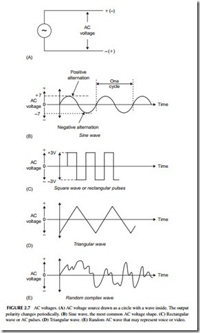
An AC voltage source is usually represented by just a circle with a varying wave inside as illustrated in Figure 2.7A. It may be the AC outlet in your home, a signal generator, or a type of electronic circuit called an oscillator. AC voltages and currents can assume many shapes. The most common electrical and electronic AC voltage is a sine wave, as shown in Figure 2.7B. The voltage rises gradually from zero to a positive peak, and then drops to zero. Then it reverses polarity, rises to a negative peak, and returns to zero. Each rise and fall is called an alternation. One positive and one negative alternation form a cycle. The cycles repeat over and over. The number of cycles that occur per second is called the frequency.
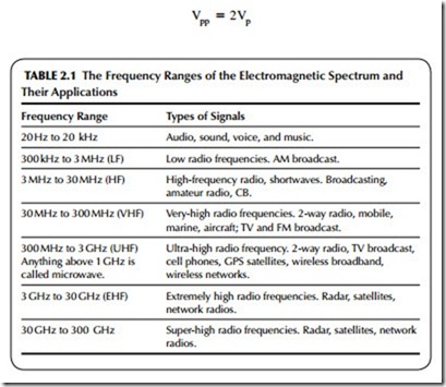
The AC power-line voltage that comes into your house and appears at the outlets is a sine wave. Its frequency is 60 cycles per second (cps). The term hertz (abbreviated Hz) is normally used instead of cps to express frequency. The power-line frequency, therefore, is 60 Hz. All radio signals are sine waves, but have very high frequencies.
AC signals can have a variety of other shapes as well. Figure 2.7C shows a square or rectangular wave. It is made up of pulses of alternating polarity volt- ages that switch from +6 to -6 volts. Figure 2.7D shows a triangular wave, and Figure 2.7E, a complex waveform that might represent voice or video. Regardless of their shape, AC signals have one thing in common: they reverse the polarity and direction of current flow periodically. Their frequencies can range from a fraction of a cycle per second to billions of cycles per second.
AC Frequency
Frequency is measured and expressed in units called cycles per second (cps) or Hz. Hertz is the more common unit. To express higher frequencies, the units kilohertz (kHz), megahertz (MHz), and gigahertz (GHz) are used.
AC Voltage Measurement
To measure or represent the amount of AC in a circuit, we usually state the peak, peak-to-peak, and root mean square (rms) values. The peak value of a wave is simply the voltage measured from the zero line to the maximum posi- tive (or negative) value. In Figure 2.7B, the peak value of the sine wave (Vp) is 7 volts. The peak-to-peak value, normally abbreviated Vpp , is the positive peak added to the negative peak. Or, since the positive and negative peaks are identical in a sine wave, the peak-to-peak value is two times the peak value, or in this case 14 volts.
Another way to measure AC voltage is to use an average value known as the root mean square (rms), or effective value. The rms value is computed by multiplying the peak value by 0.707, or:
Thus, the rms value of the sine wave is 0.707 X 7 = 4.949 volts. Most sine wave voltages are measured and stated in terms of the rms value. The amount of AC voltage available at a standard AC outlet, for example, is 120 volts rms. The rms value as discussed above is applied only to sine waves. The significance of the rms value is discussed later when we address power.


