Integrated Circuits
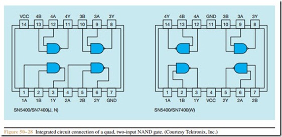
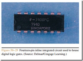
Digital logic gates are generally housed in fourteen- pin, IC packages. One of the old reliable types of TTL logic that is frequently used is the 7400 family of de- vices. For instance, a 7400 IC is a quad, two-input, positive NAND gate. The word quad means that there are four NAND gates contained in the package. Each NAND gate has two inputs, and positive means that a level one is considered to be a positive voltage.
There can, however, be a difference in the way ICs are connected. A 7400 (J or N) IC has a different pin connection than a 7400 (W) package. In Figure 50 – 28, both ICs contain four two-input NAND gates, but the pin connections are different. For this reason, it is necessary to use a connection diagram when connecting or testing integrated circuits. A fourteen-pin IC is shown in Figure 50 – 29.
Testing Integrated Circuits
Integrated circuits cannot be tested with a volt-ohm- milliammeter. Most ICs must be tested by connecting power to them and then testing the inputs and outputs with special test equipment. Most industrial equipment is designed with different sections of the control system built in modular form. The electrician determines which section of the circuit is not operating and replaces that module. The defective module is then sent to the electronics department or to a company outside of the plant for repair.
Review Questions
1. What type of digital logic operates on 5 volts?
2. What precautions must be taken when connecting CMOS logic?
3. What do the letters COSMOS stand for?
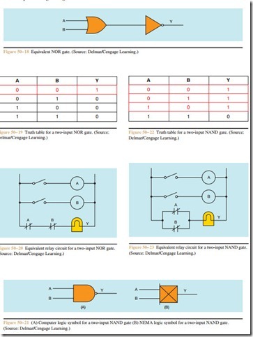
4. When using a two-input AND gate, what conditions of input must be met to have an output?
5. When using a two-input OR gate, what conditions of input must be met to have an output?
6. Explain the difference between an OR gate and an EXCLUSIVE OR gate.
7. When using a two-input NOR gate, what condition of input must be met to have an output?
8. When using a two-input NAND gate, what condition of input must be met to have an output?
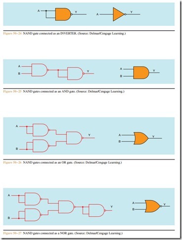
9. If an INVERTER is connected to the output of a NAND gate, what logic gate is formed?
10. If an INVERTER is connected to the output of an OR gate, what gate is formed?
11. What symbol is used to represent “invert” when computer logic symbols are used?
12. What symbol is used to represent “invert” when NEMA logic symbols are used?


