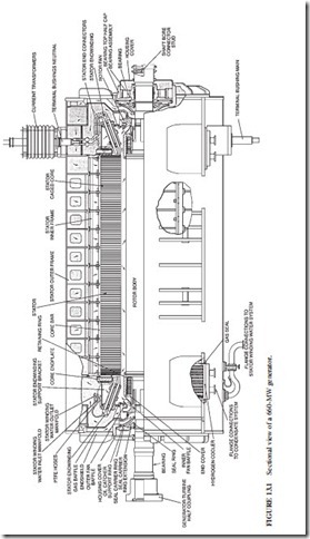
Figure 13.1 illustrates a sectional view of a large generator. Hydrogen is used to cool most generators having a rating larger than 50 MW.
THE ROTOR
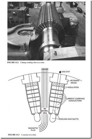
The rotor is made from a single steel forging. The steel is vacuum-degassed to minimize the possibility of hydrogen-initiated cracking. Reheating and quenching also harden the forging. Stress-relieving heat treatment is done following rough machining. Ultrasonic examination is performed at various stages of the rotor. Figure 13.2 illustrates the winding slots in the rotor. Figure 13.3 illustrates a rotor cross section and the gas flow.
The generator countertorque increases to 4 to 5 times the full-load torque when a short circuit occurs at the generator terminals. The rotor and turbine-end coupling must be able to withstand this peak torque.
Rotor Winding
Each winding turn is assembled separately in half-turns or in more pieces. The joints are at the centers of the end turns or at the corners. They are brazed together after assembling each turn, to form a series-connected coil. The coils are made of high-conductivity copper with a small amount of silver to improve the creep properties. The gas exits through radially aligned slots.
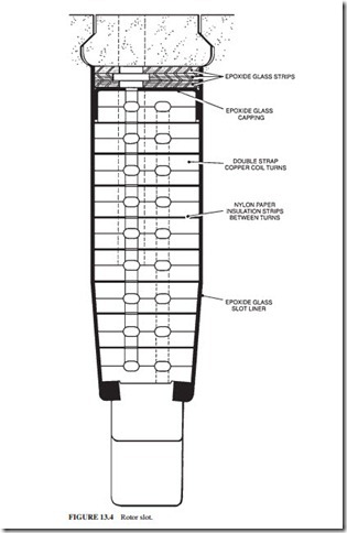
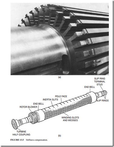
Slot liners of molded glass fiber insulate the coils. These separators of glass fiber are used between each turn. They insulate against almost 10 V between adjacent turns (Fig. 13.4). The end rings and end disks are separated from the end windings by thick layers of insulation. Insulation blocks are placed in the spaces between the end windings to ensure the coils do not distort. The winding slots are cut in diametrically opposite pairs. They are equally pitched over two-thirds of the rotor periphery, leaving the pole faces without wind- ing slots. This results in a difference between the stiffness in the two perpendicular axes. This difference leads to vibration at twice the speed. Equalizing slots are cut in the pole faces (Fig. 13.5) to prevent this problem from occurring. The slots are wider and shallower than the winding slots. They are filled with steel blocks to restore the magnetic properties. The blocks contain holes to allow the ventilating gas to flow.
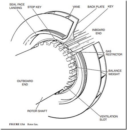
The average winding temperature should not exceed 115°C. The hydrogen enters the rotor from both ends under the end windings and emerges radially from the wedges. Figure
13.6 illustrates the fans used to drive the hydrogen through the stator.
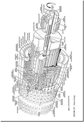
Flexible leads made of thin copper strips are connected to the ends of the winding. These leads are placed in two shallow slots in the shaft. Wedges retain them. The leads are connected to radial copper studs, which are connected to D-shaped copper bars placed in the shaft bore. Hydrogen seals are provided on the radial studs. The D leads are connected to the slip rings by radial connection bolts (Fig. 13.7).
Rotor End Rings
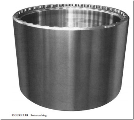
The end rings (Fig. 13.8) are used to restrain the rotor end windings from flying out under cen- trifugal forces. These rings have traditionally been made from nonmagnetic austenitic steel, typically 18% Mn, 4% Cr. A ring is machined from a single forging. It is shrunk-fit at the end of the rotor body. The material of the end rings was proved to be liable to stress corrosion cracking. A protective finish is given to all the surfaces except the shrink fit to ensure that hydrogen, water vapor, etc., do not contact the metal. The rings should be removed during long maintenance outage (every 8 to 10 years) and inspected for detailed surface cracking using a fluorescent dye. Ultrasonic scanning is not sufficient due to the coarse grain structure. A recent
development has proved that austenitic steel containing 18% Mn and 18% Cr is immune to stress corrosion cracking. New machines use this alloy. It is also used for replacement rings. This eliminates the need for periodic inspection. It is important to mention that a fracture of an end ring can result in serious damage to the machine and at least a few months’ outage. It is highly recommended to replace the traditional material with the new material.
The rings must be heated to 300°C to expand sufficiently for the shrink surface. Induction heating is preferred to direct heating to prevent possible damage to the rings. The end ring is insulated from the end winding with a molded-in glass-based liner or a loose cylinder sleeve. Hydrogen enters the rotor in the clearance between the end winding and the shaft. The outboard end of the ring is not permitted to contact the shaft, to prevent the shaft flexure from promoting fatigue and fretting damage at the interfaces. A balancing ring is also included in the end disk for balancing the rotor.
Wedges and Dampers
Wedges are used to retain the winding slot contents. Wedges are designed to withstand stresses from the windings while allowing the hydrogen to pass through holes. They must also be nonmagnetic to minimize the flux leakage around the circumference of the rotor. They are normally made of aluminum. One continuous wedge is used for each slot.
During system faults or during unbalanced electrical loading, negative phase sequence currents and fluxes occur, leading to induced currents in the surface of the rotor. These cur- rents will flow in the wedges which act as a “damper winding” similar to the bars in the rotor of an induction motor. The end rings act as shorting rings in the motor. Arcing and localized pitting may occur between the end rings and the wedges.
Slip Rings, Brush Gear, and Shaft Grounding
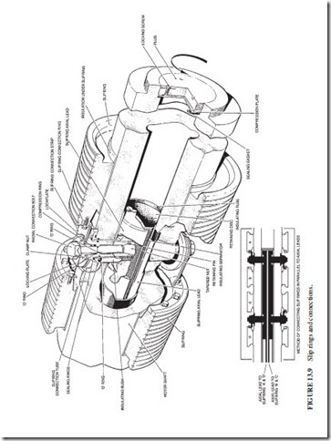
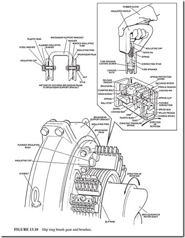
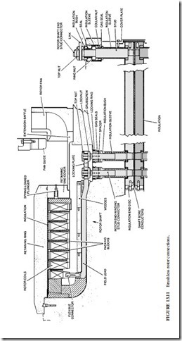
The D leads in the bore are connected through radial copper connectors (which normally have backup hydrogen seals) and flexible connections to the slip rings (Fig. 13.9). The exci- tation current is around 5000 A dc for a 660-MW generator. The surface area of the slip rings must be large to run cool while transferring the current. Figure 13.10 illustrates the brush gear including brushes and holders of a removable bracket. The holders can be replaced on power. Constant-pressure springs are used to maintain brush pressure. A brush life should be at least 6 months. A separate compartment houses the brush gear. A shaft-mounted fan provides separate ventilation so that brush dust is not spread on other excitation components. Small amounts of hydrogen may pass through the connection seals and may accumulate in the brush gear compartments during extended outages. The fan dilutes them safely during start-up before excitation current is applied. The brush gear can be easily inspected through windows in the cover. Figure 13.11 illustrates brushless rotor connections.
A large generator produces normally an on-load voltage of 10 to 50 V between its shaft ends due to magnetic dissymmetry. This voltage drives an axial current through the rotor body. The current returns through bearings and journals. It causes damage to their surfaces. Insulation barriers are installed to prevent such current from circulating. The insulation is installed at all locations where the shaft could contact earthed metal, e.g., bearings, seals, oil scrapers, oil pipes, and gear-driven pumps.
Some designs have two layers with a “floating” metallic component between them. The integrity of insulation is confirmed by a simple resistance measurement between the float- ing component and earth.
If the insulation remains clean and intact, a difference in voltage will exist between the shaft at the exciter end and ground. This provides another method to confirm the integrity of the insulation. The shaft voltage is monitored by shaft-riding brush. An alarm is initiated when the shaft voltage drops below a predetermined value.
It is important to maintain the shaft at the turbine end of the generator at ground level. A pair of shaft riding brushes ground the shaft through a resistor. Since carbon brushes develop a high-resistance glaze when operated for extended periods without current flow, a special circuit introduces a wetting current into and out of the shaft through the brushes. This circuit also detects loss of contact between the brush and the shaft.
Fans
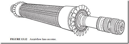
Fans drive the hydrogen through the stator and the coolers. Two identical fans are mounted at each end of the shaft. Centrifugal or axial-type fans are used (Fig. 13.12).
Rotor and Alignment Threading
The stator bore is about 25 cm larger than the rotor diameter. The rotor is inserted into the stator by supporting the inserted end of the rotor on a thick steel skid plate which slides into the stator, while the outboard end is supported by a crane.
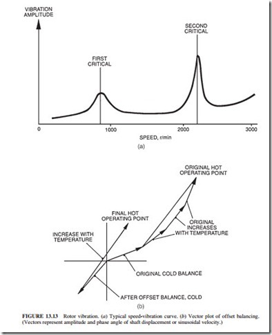
Generator rotors rated at 500 to 600 MW have two main critical speeds (natural resonance in bending). Simple two-plane balancing techniques are not adequate to obtain the high degree of balance required and to ensure low vibration levels during run-up and rundown. Therefore, balancing facilities are provided along the rotor in the form of taped holes in cylindrical surfaces. The manufacturer balances the rotor at operating speed. The winding is then heated, and the rotor is operated at 20 percent overspeed. This allows the rotor to be subjected to stresses higher than the ones experienced in service. Trim balancing is then conducted, if required. There is a relationship between vibration amplitude and tempera- ture in some rotors. For example, uneven ventilation can create a few degrees difference in temperature between two adjacent poles. This effect can be partially offset by balancing to optimize the conditions at operating temperature (Fig. 13.13).
Uneven equalization of stiffness will cause vibration having a frequency of twice the operating speed. It is important to distinguish between the vibration caused by unbalance (occurring at 1 times the operating speed) and equalization of stiffness. A large crack in the rotor will have relatively larger effect on the double frequency vibration component. Vibration signals during rundown are analyzed and compared with the ones obtained in previous rundowns. Oil whirl in bearings can cause vibration at one-half the speed. The amplitude and phase of vibration are recorded at the bearings of the generator and exciter, using accelerometers mounted on the bearing supports and by proximity probes, which detect shaft movements.
Bearings and Seals
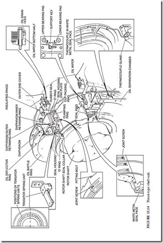
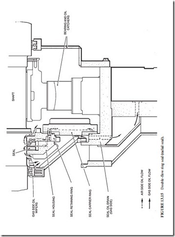
The generator bearings are spherically seated to facilitate alignment. They are pressure- lubricated, have jacking-oil taps, and are insulated from the pedestals. Seals (Fig. 13.14) are provided in the end shields to prevent hydrogen from escaping along the shaft. Most seals have a nonrotating white-metal ring bearing against a collar on the shaft. Oil is fed to an annular groove in the ring. It flows radially inward across the face into a collection space and radially outward into an atmospheric air compartment. The seal ring must be maintained against the rotating collar. Therefore, it must be able to move axially to accom- modate the thermal expansion of the shaft. Figure 13.15 illustrates a seal that resembles small journal bearings (radial seal). The oil is applied centrally. It flows axially inward to face the hydrogen pressure. It also flows axially outboard into an atmospheric compart- ment. The seal does not have to move axially, because the shaft can move freely inside it. This is a major advantage over the seal design illustrated in Fig. 13.14. Most generators use radial seals.
Size and Weight
The rotor of a 660-MW generator is up to 16.5 m long and weighs up to 75 tons. The rotor must never be supported on its end rings. The weight must be supported by the body sur- face. The rotor must also be protected from water contamination, while in transient or stor- age. A weatherproof container with an effective moisture absorbent must be used. If the rotor is left inside an open stator, dry air must be circulated.
