DC SERIES MOTOR:
Speed control is achieved by adjusting the field ampere turns. There are three ways for varying the field ampere turns.
1. DIVERTER FIELD CONTROL:
Diverter resistance Rdis connected across the field winding as shown in Figure 2.14. By varying Rd the field current and hence the field ampere turns can be reduced. Therefore, the field current is given by
From the above equation speed torque characteristics for decreasing values of Kd are plotted which is shown in above Figure 2.15.
2. Tapped field control:
The field ampere turns are adjusted in steps by varying the number of turns included in the circuit as shown in figure 2.16, the following relations are obtained from the circuit.
The speed torque characteristics are shown in figure 2.17 and are of similar to those of diverter field control.
3. Series parallel control:
In this method, the field windings are divided into two equal halves and then connected in series or parallel to control the field ampere turns as shown in figure 2.18 and 2.19 respectively.
COMPARISION OF TORQUE DEVELOPED BY MOTORS IN SERIES AND PARALLEL CONNECTION:
MOTORS IN SERIES:
From equations 33 and 34 torque developed in series connection is four times that of motors in parallel connection.
ARMATURE VOLTAGE CONTROL:
In this method, applied voltage across the armature of the DC motor is varied. This method is superior to field control in the following aspects:
1. This method provides a constant torque drive.(if the <l and Ia are maximum, maximum torque can be obtained as T ![]() <l Ia)
<l Ia)
2. Since main field ampere turns are maintained at large value, flux density distortion caused by armature reaction is limited.
3. Unlike field control scheme, speed reversal can be easily implemented. This method requires a variable voltage supply which makes this method costlier. DC SHUNT MOTOR:
Following are the armature control schemes for DC shunt motor.
1. Rheostatic control:
Here the applied armature voltage is varied by placing an adjustable resistance ‘R’ in series with the armature as shown in the Figure 2.22. N vs T for varying ‘R’ is shown in figure 2.23.
Some of the limitations of the rheostatic method are:
1. Speeds only below rated speed
2. Range of speeds is limited because efficiency reduces drastically for large speed reductions
3. Speed regulation is poor. Because for a given resistance re, N varies directly with load.
Therefore this method is suitable for very small (fractional kW) or for short-time, intermittent slowdowns for medium sized motors.
1. Shunted armature control:
In the armature rheostatic control method, the change in armature current due to change in load will affect the speed. Hence in this method the armature is shunted by an adjustable resistance as shown in Figure 2.25.
SERIES PARALLEL CONTROL OF SHUNT MOTOR:
In this method the two identical motors are coupled together mechanically to a common load. Two speeds at constant torque are possible in this method – one by connecting motor armature in series and the other by connecting them in parallel as shown in figures 2.26 and 2.27 respectively. When connected in series the voltage across each motor is half the supply voltage and when in parallel, each armature carries full supply voltage.
This method is superior to rheostatic control so far as efficiency is concerned but the speeds that can be obtained can only be two steps. This method is commonly employed for speed control of series traction motors.
WARD-LEONARD METHOD OF SPEED CONTROL:
It is a combined armature and field control and is therefore operationally the most efficient method of speed control with a wide range. ‘M’ is the main motor whose speed control is required. The field of this motor is permanently connected across the DC supply lines. Its armature is supplied by a variable voltage derived by a polyphase Induction Motor-DC generator set. The field of the DC generator is excited from an exciter coupled to the extension of the induction motor shaft. The entire arrangement is shown in the figure 2.28. The reversible switch provided for the generator makes it possible to easily reverse the generator excitation thereby reversing the voltage polarity for reversing the direction of rotation of motor. Though expensive, this arrangement can be easily adapted to feedback schemes for automatic control of speed. This method provides both constant torque and constant HP (or kW) drive.
The motor armature and its field winding are fed at maximum values at the base speed Nbase. Reducing armature voltage provides a constant torque speed control where the speed can be reduced below the base value, while the motor has full torque capability. For obtaining speeds above Nbase the field is gradually weakened. The motor torque therefore reduces as its speed increases which corresponds to constant kW (or HP) drive. This is shown in the Figure 2.29.
Some of the features of the Ward Leonard system are given below:
1. Absence of external resistance improves efficiency at all speeds and also when the generator emf becomes less than the back emf of the motor, the electrical power flows back from motor to generator, is converted to mechanical form and is returned to the mains via the driving AC motor.
2. Motor starts up smoothly therefore No starting device is required.
3. Speed reversal is smoothly carried out.
4. Fine speed control from zero to rated value in both the directions.
This method of speed control is used in
a. High speed elevators
b. Colliery winders
Advantages
1. Absence of external resistance improves efficiency at all speeds
2. Motor starts up smoothly. No starting device is required
3. Speed reversal is smoothly carried out
STARTERS FOR DC MOTORS
Necessity of starter:
The current drawn by the armature is given by![]()
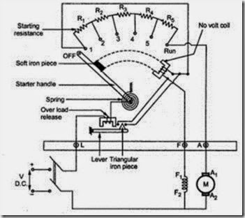
Armature resistance will be very low. Therefore, the current drawn by the motor will be very high. In order to limit this high current, a starting resistance is connected in series with the armature. The starting resistance will be excluded from the circuit after the motor attains its rated speed. From there on back emf limits the current drawn by the motor. The arrangement is shown in the figure 2.30 which is a three point starter for shunt motor.
Three Point Starter:
It consists of resistances arranged in steps, R1to RSconnected in series with the armature of the shunt motor. Field winding is connected across the supply through a protective device called ‘NO – Volt
Coil’. Another protection given to the motor in this starter is ‘over load release coil’. The arrangement is shown in Figure 2.30
To start the motor the starter handle is moved from OFF position to Run position gradually against the tension of a hinged spring. An iron piece is attached to the starter handle which is kept hold by
Figure 2.30
the No-volt coil at Run position. The function of No volt coil is to get deenergised and release the handle when there is failure or disconnection or a break in the field circuit so that on restoration of supply, armature of the motor will not be connected across the lines without starter resistance. If the motor is over loaded beyond a certain predetermined value, then the electromagnet of overload release will exert a force enough to attract the lever
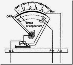
which short circuits the electromagnet of No volt coil. Short circuiting of No volt coil results in deenergisation of it and hence the starter handle will be released and return to its off position due to the tension of the spring. In this type of starter, the shunt field current has to flow back through the starter resistance thus decreasing the shunt field current. This can be avoided by placing a brass arc on which the handle moves as shown in Figure 2.31.
Figure 2.31
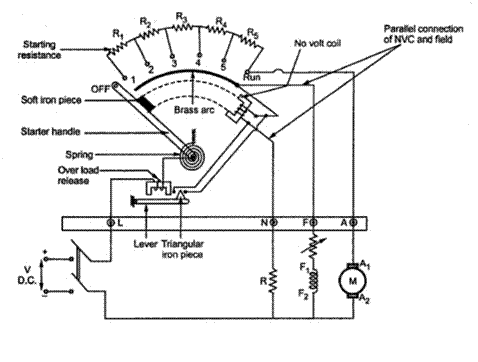
FOUR POINT STARTER: Figure 2.32 shows a four point starter.
 One important change is the No Volt Coil has been taken out of the shunt field and has been connected directly across the line through a Protecting resistance ‘R’. When the arm touches stud one. The current divides into three paths, 1. Through the starter resistance and the armature, 2. Through shunt field and the field rheostat and 3.Through No-volt Coil and the protecting resistance ‘R’. With this arrangement, any change of current in shunt field circuit does not affect the current passing though the NO-volt coil because, the two circuits are independent of each other. Thus the starter handle will not be released to its off position due to changes in the field current which may happen when the field resistance is varied.
Application of DC Motors:
DC Series Motor:
1. Starting torque is very high up to the five times the full load torque.
2. Speed regulation of the DC series motor can be varied widely.
3. Are used in hoists, cranes, battery powered vehicles, electric traction, etc.
DC Shunt Motor:
1. Has a medium starting torque.
2. Speed regulation is 5 to 15%.
3. It is essentially used for constant speed applications requiring medium starting torques such as centrifugal pumps, fans, blowers, conveyors, machine tools, printing presses etc.
DC Compound Motor:
1. Its characteristics depend on degree of compounding.
2. It has considerably high starting torque and drooping speed – load characteristics.
3. Used for varying loads such as shears, conveyors, crushes, punch presses, hoists, rolling mill, milling machines etc.


