DC MOTORS
DC motor operates on the principle that when a current carrying is placed in a magnetic field, it experiences a mechanical force given by F = BIL newton. Where ‘B’ = flux density in wb/m2, ‘I’ is the current and ‘L’ is the length of the conductor. The direction of force can be found by Fleming’s left hand rule. Constructionally, there is no difference between a DC generator and DC motor.
Figure 2.1 shows a multipolar DC motor. Armature conductors are carrying current downwards under North Pole and upwards under South Pole. When the field coils are excited, with current carrying armature conductors, a force is experienced by each armature conductor whose direction can be found by Fleming’s left hand rule. This is shown by arrows on top of the conductors. The collective force produces a driving torque which sets the armature into rotation.
The function of a commutator in DC motor is to provide a continuous and unidirectional torque.
In DC generator the work done in overcoming the magnetic drag is converted into electrical energy. Conversion of energy from electrical form to mechanical form by a DC motor takes place by the work done in overcoming the oppos tion which is called the ‘back emf’.
BACK EMF: is the dynamically induced emf in the armature conductors of a dc motor when the armature is rotated. The direction of the induced emf as found by Flemings right hand rule is in opposition to the applied voltage. Its value is same as that of the induced emf in a DC generator ![]() This emf is called as back emf’Eb. The work done in overcoming this opposition is converted into mechanical energy.
This emf is called as back emf’Eb. The work done in overcoming this opposition is converted into mechanical energy.
SIGNIFICANCE OF BACK EMF: Figure 2.2 shows a DC shunt motor. The rotating armature
generating the back emf’Eb is like a battery of emf ‘Eb connected across a supplyvoltage of ‘V’ volts.
If Eb is large, armature current will be less and vice versa. Hence Eb acts like a governor i.e., it makes the motor self- regulating so that it draws as much current as required by the motor.
VOLTAGE EQUATION OF A MOTOR:
The voltage ‘V’ applied across the motor armature has to
i) Overcome the back emf Eb and
ii) Supply the armature ohmic drop Ia ra
Hence V = Eb + Ia ra…..1 This is known as voltage equation of DC motor.
Multiplying both sides of voltage equation by Ia
Thus the mechanical power developed by the motor is maximum when the back emf is equal to half the applied voltage.
TORQUE:
Torque is the twisting moment about an axis. It is measured by the product of the force and the radius at which the force acts. Consider a pulley of radius ‘r’ metre acted upon a circumferential force of ‘F’ newton which causes it to rotate at ‘N’ rotations per second (r.p.s) as show in Figure. 2.3
ARMATURE TORQUE OF A MOTOR:
SHAFT TORQUE (TSH):
Some of the torque developed in the armature will be lost in supplying the iron and friction losses in the motor. The torque which is available for doing useful work is known as shaft torque ‘Tsh’. The horse power obtained by using the shaft torque is called as Brake Horse Power (BHP).
Speed regulation: is defined as the change in speed from No-load to full load when the rated load on the motor is reduced to zero, expressed as a percentage of rated speed.
CHARACTERISTICS OF DC MOTORS:
There are three important characteristics.
1. Armature torque vs Armature current Tavs Ia (Electrical characteristics)
2. Speed vs armature current characteristic
3. Speed vs torque N vsTa (Mechanical characteristics)
CHARACTERISTICS OF SHUNT MOTORS
1. Tavs faCHARACTERISTICS
For a shunt motor flux can be assumed practically constant (at heavy loads, decreases, due to increased armature reaction)
Therefore electrical characteristic of a shunt motor is a straight line through origin shown by dotted line in Figure 2.4. Armature reaction weakens the flux hence Ta vs Ia characteristic bends as shown
by dark line in figure 2.4, Shunt motors should never be started on heavy loads, since it draws heavy current under such condition.
2. N vs faCHARACTERISTICS
N ∝ Eb ; Eb is practically almost constant.
Hence the speed is constant. However, Eb decreases slightly more than with increase in load and thus there is slight decrease in speed. This decrease in speed varies from 5 to 15% of full load speed
and it depends on armature reaction and saturation. This characteristics is shown in Figure 2.5
3. N vs TaCHARACTERISTICS
This characteristic can be deduced from 1 and 2, shown in figure 2.6
Performance curves of DC shunt motor
The four essential characteristics of shunt motor i.e., torque, speed, current and efficiency plotted as a function of horse power are known as performance curves of the motor, shown in figure 2.7
Shunt motor has a definite No-load speed hence can be used where a load is suddenly thrown off with field circuit remaining close. The drop in speed from No-load to full load is small and hence referred to as constant speed motor. The efficiency curve is usually of the same shape for all motors and generators. It is advantageous to have an efficiency curve which is fairly flat and the maximum efficiency near to full load. Certain value of minimum current is required even when the output is zero as the input under No-load condition has to meet the losses within the machine.
The shunt motor is also capable of starting under heavy load condition but the current drawn by the motor will be very high (Ta ∝ Ia )compared to DC series motor. As the series motor draws only one and half times the full load currentTa ![]()
CHARACTERISTICS OF SERIES MOTORS
At light loads, Iaand hence is small. But as Iaincreases Ta increases as the square of the current up to saturation. After saturation becomes constant, the characteristic becomes a straight line as shown in Figure 2.8. Therefore a series motor develops a torque proportional to the square of the armature current. This characteristic is suited where huge starting torque is required for accelerating heavy masses.
This characteristic is shown in figure 2.9(a). Change in Eb for various load currents is small. Hence may be neglected. Therefore the speed is inversely proportional to flux, because . When the load is heavy, Ia is large and speed is low. When the load is low, current and hence flux will be small. Therefore speed becomes dangerously high. Hence a series motor should never be started without load on it.
PERFORMANCE CURVES OF DC SERIES MOTOR
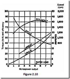
The performance curves of DC series motor are shown in Figure 2.10. The machine is so designed that it is having maximum efficiency near rated load.
For a given input current, the starting torque developed by a DC series motor is greater than shunt motor. Hence series motors that developed by a are used where huge starting torques are necessary. Ex. Cranes, hoists, electric traction etc. The DC series motor responds by decreasing its speed for the increased in load. The current drawn by the DC series motor for the given increase in load is lesser than DC shunt motor. The drop in speed with increased load is much more prominent in series motor than that in a shunt motor. Hence series motor is not suitable for applications requiring a constant speed.
COMPOUND MOTOR CHARACTERISTICS
Cumulative compound motors:
are used where series characteristics are required and in addition the load is likely to be removed totally such as in some types of coal cutting machines or for driving heavy machine tools which have to take sudden deep cuts quite often. Speed will not become excessively high due to shunt winding and the motor will because of series winding.
Differential compound motors: Series field opposes the shunt field; therefore the flux is decreased as the load is applied to the motor. This results in the motor speed remaining almost constant or even increasing with increase in load.
Summarizing,
2. Used in rolling mills where light and heavy loads are thrown on the motor.
3. Cumulative compound motor has a finite No-load speed and has a load – relieving characteristics of a series motor under heavy load conditions.
4. Differential compound motors are seldom used in practice.(because of rising speed characteristics)
SPEED CONTROL OF DC MOTORS
DC motors are in general much more adaptable speed drives than AC motors. Speed of a DC motor can be controlled in a wide range.
From the above equation, two methods of speed control are possible.
1. Variation of field current which varies the flux/pole (<l) and is known as field control.
2. Variation of terminal voltage ‘V’ known as armature voltage control.
FIELD CONTROL:
For a fixed terminal voltage,![]() (for linear magnetization) …………..22
(for linear magnetization) …………..22
Limitations of speed control by field control:
1. ‘N’ below rated speed is not possible. Because <l can be decreased and cannot increase.
2. Noc 1 &T oc 4J for a given armature current, this method suits for constant kW drives only
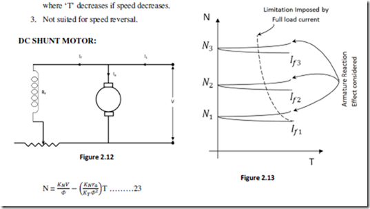
Speed control is achieved by means of a rheostat in the field circuit as shown in the Figure 2.12. The speed torque characteristics have a small linear drop due to the second term (ra effect) in the above equation. The field is weakened due to the armature reaction. The working range of the speed torque characteristics reduces with increasing speed in order for the armature current not to exceed the full load value with a weakening field. The speed – torque curves are shown in Figure 2.13
Related posts:
Incoming search terms:
- full load shaft torque formular
- using a sutable formulae explain why current drawen by dc moto increases whe motor is machenically loaded
- torque speed characteristics of dc motor
- shunt Motor BHP formula
- applied voltage control of dc shunt motor can not be used in practice
- How to get finite no load speed in dc series motor
- In dc motor Eb maximum at_____
- load current vs out put power graph in DC shut motor
- picture of the graph of effieciency against output power for a shunt dc motor
- plotting curve of dc shunt generator picture
- speed formula for dc series and shuntmotor
- speed regulation formula
- using the concept of mechanical drag and back emf show that dc nachine is a converter of energy for converting electrical energy into mechanical energy and vice versa
- four essential characteristic performance curves of a dc shunt motor
- for dc shunt motor output power vs efficiency graph
- back emf acts as a governor for dc motors
- BHP formula for dc series motor
- bhp formula of load test on dc shunt motor
- brake horsepower formula for dc series motor
- brake horsepower formula for shunt motors
- comment on efficiency curve of dc shunt motor
- dc motor current vs torque v curve
- DC motor shaft power formula
- efficiency curve of dc shunt motor
- electric motor efficiency curve
- emf calculations of a dc shunt Moto
- explain using suitable formulae why the current drawn by this motor increase when the motor is mechanically loaded
- Voltage applied across the shunt motor has to 1 Overcome the back emf 2 Supply armature ohmic drop 3 supply field ohmic drop 4 Both 2 and 3


