POLYPHASE MACHINES
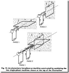
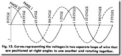
A two-phase generator is actually a combination of two single-phase generators, as shown in Fig. 12. The armatures of these two machines are mounted on one shaft and must revolve together, always at right angles to each other. If the voltage waves or curves are plotted as in Fig. 13, it will be found that when phase 1 is in such a position that the voltage is at a maximum, phase 2 will be in such a position that the voltage in it is zero. A quarter of a cycle later, phase 1 will be zero and phase 2 will have advanced to a position previously occupied by 1, and its voltage will be at a maximum. Thus, phase 2 follows phase 1 and the voltage is always exactly a quarter of a cycle behind because of the relative mechanical positions of the armatures
It has been found economical to have more than one coil for each pole of the field. Because of this, present-day ac generators are built as three-phase units in which there are three sets of coils on the armature. These three sets of armature coils may each be used separately to supply electricity to three separate lighting circuits.
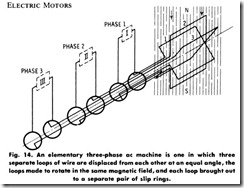
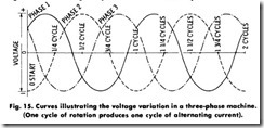
In a three-phase generator, three single-phase coils (or windings) are combined on a single shaft and rotate in the same magnetic field, as shown in Fig. 14. Each end of each coil is brought out through a slip ring to an external circuit. The voltage in each phase alternates exactly one-third of a cycle after the one ahead of it because of the mechanical arrangement of the windings on the armature. Thus, when the voltage in phase 1 is approaching a maximum positive, as shown in Fig. 15, the voltage in phase 2 is at a maximum negative, and the voltage in phase 3 is declining. The succeeding variations of these voltages are as indi cated.
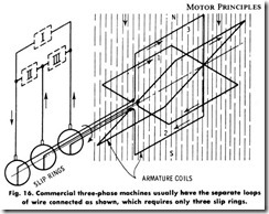
In practice, the ends of each phase winding are not brought out to separate slip rings, but are connected as shown in Fig. 16. This arrangement makes only three leads necessary for a three-phase wind
ing, each lead serving two phases. This allows each pair of wires to actlike a single-phase circuit that is substantially independent of the other phases.
Revolving Magnetic Field
In the diagrams studied thus far, the poles producing the magnetic field have been stationary on the frame of the machine, and the armature in which the voltages are produced rotates. This arrangement is un iversally employed in direct-current machines, but alternating-current motors and generators generally have revolving fields because of the need for only two slip rings.
When the revolving-field construction is employed, the two slip rings need only carry the low-voltage exciting current to the field. For a three-phase machine with a rotating armature, at least three slip rings would be required for the armature current, which is often at a high voltage and therefore would require a large amount of insulation, adding to the cost of construction. A schematic of a single-phase ac generator with revolving field is shown in Fig. 17. The operation of practically all polyphase alternating-current motors depends on a re volving magnetic field which pulls the rotating part of the motor around with it.
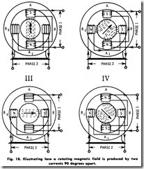
To produce a rotating field, assume that two alternating currents of the same frequency and potential, but differing in phase by 90 degrees, are available. Connect them to two sets of coils wound on the inwardly projecting poles of a circular iron ring, as illustrated in Fig. 18. It will be noted that when the current in phase 1 is at a maximum, the current in phase2 is zero. Poles A andA, are magnetized, while polesB andB, are demagnetized. The magnetic flux is in a direction from N to S, as indicated by the arrow.
Referring to the voltage curves, it will be found that one-eighth of a Cj’cle (45°) later, the current in phase 1 has decreased to the same value to which the current in phase 2 has increased. The four poles are now equally magnetized, and the magnetic flux takes the direction of the arrow shown in diagram II.
One-eighth of a cycle later, the current in phase 1 has dropped to zero, while the current in phase 2 is at its maximum. With reference to diagram III, in Fig. 18, this condition indicates that poles A and A, are demagnetized, but that poles B and B, are magnetized, with the flux from N to S, as shown by the arrow.
Continuing the analysis, notice that after an additional one-eighth of a cycle, the current in both phases 1 and 2 has decreased and that the four poles are again equally magnetized, with the magnetic flux in the direction as indicated by the arrow in diagram IV. If this process is
continued at successive intervals during a complete period or cycle of change in the alternating current, the magnetic flux represented by the arrow will make a complete revolution for each cycle of the current.
This action of the current is inducing a rotating magnetic field which would cause a magnet to revolve on its axis according to the periodicity of the impressed alternating current. This analysis explains the action in a two-phase motor. The rotating magnetic field in a three-phase ac motor having any number of poles can be similarly obtained.
Synchronous Motors
Any ac generator can be employed as a motor, provided that it is first brought up to the exact speed of a similar generator supplying the current to it, and provided that it is then put in step with the alternations of the supplied current. Such a machine is called a synchronous motor. Because, however, of complications in starting, most synchronous motors of late construction are equipped with a damper or amortisseur winding which produces a starting torque, permitting them to be started as induction motors.
The speed of a synchronous motor depends on the frequency of the current supplied to it and the number of poles in the motor.
The equation for the speed is:
Since a synchronous motor runs at exactly this speed, it is a relatively simple matter to calculate the speed of any motor, provided that the number of poles and the frequency of the source are known. Thus, for example, an eight-pole synchronous motor operating from a 60-hertz source has a speed of:
Induction Motors
Although the synchronous motor is used commercially in certain applications, the induction motor is used more extensively because of its simplicity. There are two principal classes of polyphase induction motors, namely:
1. Squirrel cage.
2. Wound rotor.
By definition, an induction motor is one in which the magnetic field in the rotor is induced by currents flowing in the stator. The rotor has no connections whatever to the supply line.
Squirrel-Cage Motor-This type of induction motor consists of a stator which is identical to the armature of a synchronous motor, and has a “squirrel-cage” rotor with bearings to support it. Because the stator receives the power from the line, it is often called the primary and the rotor the secondary.
In an induction motor of this type, the squirrel-cage winding takes the place of the field in the synchronous motor. The squirrel cage consists of a number of metal bars connected at each end to supporting metal rings. As in the synchronous motor, a rotating field is set up by the currents in the armature.
As this field revolves, it cuts the squirrel-cage conductors, and voltages are set up in them exactly as though the conductors were cutting the field in any other motor. These voltages cause current to flow in the squirrel-cage circuit, through the bars under the north poles into the ring, back to the bars under the adjacent south poles, into the other ring, and back to the original bars under the north pole, completing the circuit.
The current flowing in the squirrel cage, down one group of bars and back in the adjacent group, makes a loop which establishes magnetic fields with north and south poles in the rotor core. This loop consists of one turn, but there are several conductors in parallel and the currents may be large. These poles in the rotor, attracted by the poles of the revolving field, set up the currents in the armature winding, and follow them around in a manner similar to that in which the field poles follow the armature poles in a synchronous motor.
There is, however, one interesting and important difference between the synchronous motor and the induction motor-the rotor of the latter does not rotate as fast as the rotating field in the armature. If the squirrel cage were to go as fast as the rotating field, the conductors in it would be standing still with respect to the rotating field, rather than cutting across it. Thus, there could be no voltage induced in the squirrel cage, no currents in it, no magnetic poles set up in the rotor, and no attraction between it and the rotating field in the stator. The rotor revolves just enough slower than the rotating field in the stator to allow the rotor conductors to cut the rotating magnetic field as it slips by, and thus induces the necessary currents in the rotor windings.
This means that the motor can never rotate quite as fast as the revolving field, but is always slipping back. This difference in speed is called the slip. The greater the load, the greater the slip will be-that is, the slower the motor will run-but even at full load, the slip is not too great. In fact, this motor is commonly considered to be a constant-speed device. The various classes of squirrel-cage motors, and their operation and control, are given in a later chapter.
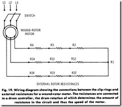
Wound-Rotor Motor-This type of induction motor differs from the squirrel-cage type in that it has wire-coil windings in it instead of a series of conducting bars in the rotor. These insulated coils are grouped to form definite polar areas having the same number of poles as the stator. The rotor windings are brought out to slip rings whose brushes are connected to variable external resistances (Fig. 19).
By inserting external resistance in the rotor circuit when starting, a high torque can be developed with a comparatively low starting current. As the motor accelerates up to speed, the resistance is gradually reduced until, at full speed, the rotor is short-circuited. By varying the resistance in the rotor circuit, the motor speed can be regulated within practical limits.
This method of speed control is well suited for the wound-rotor motor because it is already equipped with a starting resistance in each phase of the rotor circuit. By making these resistances of large enough current carrying capacity to prevent dangerous heating in continuous service, the same resistances can also serve for regulation of the speed. Al though effective speed control is best secured by the use of direct-cur rent motors, the wound-rotor motor, because of its adjustable rotor resistance, possesses one of the few methods of speed control available for alternating-current motors.
Slip
The speed of a synchronous motor is constant for any given fre quency and number of poles in the motor. In an induction motor, however, this exact relationship does not exist, because the rotor slows down when the load is applied. The ratio of the speed of the field (relative to the rotor) to synchronous speed is termed the slip. It is usually written:
where,
s is the slip (usually expressed as a percentage of synchronous speed),
Ns is the synchronous speed,
N is the actual rotor speed.
For example, a six-pole, 60-hertz motor would have a synchronous speed of 1200 r/min. If its rotor speed were 1164 r/min, the slip would be:
