A cycloconverter has as its input the three-phase ac Hne and produces as an output
a nonsinusoidal ac voltage at a lower frequency. A single cycloconverter produces
a single-phase output voltage. To control the speed of a three-phase ac motor,
induction or synchronous, we use three cycloconverters. We just arrange for their
gate firing pulses to be offset in time, so that their three output voltages are phasedisplaced by 120°. The three individual cycloconverters then drive the three individual stator windings of the three-phase ac motor.
15-10-1 Six-SCR Cycloconverters
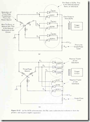
A cycloconverter can be built with either six SCRs or 12 SCRs. Figure 15-15(a)
shows the circuit schematic for the six-SCR design. By convention, the SCRs are
labeled with odd numbers only. They are labeled this way so that the gate pulsing
sequence is always in ascending order, whether the cycloconverter is built with six
SCRs or 12 SCRs. This idea will become clear when we make a close examination
of cycloconverter waveforms.
In the cycloconverter of Fig. 15-15(a), three particular SCRs are responsible
for producing the positive half-cycle of the output waveform; they are SCRs 1, 3
and 5. The remaining three SCRs, 7, 9 and 11, are responsible for producing the
negative half-cycle. We find it convenient to mentally group the SCRs together on
this basis. Fig. 15-15(b) is the same circuit as Fig. 15-15(a), but with the SCRs
grouped as described. Let us adopt the phrase positive triplet to refer to the group
that produces the positive half-cycle (numbers 1, 3 and 5), and negative triplet for
the negative-half cycle group (numbers 7, 9 and 11). This nomenclature is used in
Fig. 15′-15(b).
The cycloconverter’s trigger circuit delivers gate pulses to the SCRs, basically
at the rate of one gate pulse for each pulsation of the three-phase ac line (basically
180 gate pulses per second, for the six-SCR design used with a 60-Hz ac line). The
output frequency is determined by the number of gate pulses per half-cycle of the
output waveform. In plain terms, if the trigger circuit delivers only a small number
of sequential gate pulses to one triplet before it changes over to deliver the same
number to the other triplet, then each triplet will remain in conduction for only a
short time. This corresponds to a short time duration for each half-cycle of the
output waveform, causing the output frequency to be high. But on the other hand,
if the trigger circuit delivers a large number of sequential gate pulses to each triplet
before changing over, then each triplet will remain in conduction for a long time,
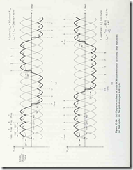
causing the output frequency to be low. To clarify this concept, refer to the
waveforms of Fig. 15-16.
In Fig. 15- 16(a), the trigger circuit is delivering four sequential gate pulses
to each triplet. The pulses are delivered in ascending order, as they were for inverter
operation in Sees. 15-8 and 15-9. In this case the pulses are timed to produce a
steady firing delay angle of 30°; that is, every SCR is gated ON 30° after its associated
ac line phase crosses through zero. To keep things simple for now, we’ll assuine
that the cycloconverter’s trigger circuit operates this way, giving a steady firing
delay angle.
At the left of Fig. 15-16(a), the four sequential gate pulses turn ON one SCR
at a time, in the order 1, 3, 5, 1. The load voltage waveform thus consists of
segments of the phase voltages, with the segments 120° wide and centered on their
positive peaks. Commutation of the SCRs is natural, because firing at or later than
30° enables the new SCR to apply a reverse bias to the previously-ON SCR.
When the trigger circuit is finished with the positive triplet, it delivers a
matching pulse sequence to the negative triplet, thereby forming the negative halfcycle of Kld- It then returns to the positive triplet to begin the next cycle of load
voltage.
In Fig. 15- 16(a), one cycle of V,^ corresponds to three cycles of the ac line
voltage, so the output (load) frequency is one-third of the ac line frequency. Verify
this for yourself by examining the waveform.
In Fig. 15-16(b) the trigger circuit has been adjusted to give six sequential
gate pulses per triplet, again at a steady 30° delay angle. The greater number of
gate pulses causes the output frequency to decrease. In this case one output cycle
takes four line cycles plus 150°, or 4n line cycles. For a 60-Hz line,
60 Hz
,
,
.![]()
4 Vn
Verify this for yourself.
For this frequency setting, the trigger circuit does not begin each cycle of
load voltage with the same SCR. Note that the first cycle in Fig. 15-16(b) begins
with SCRl but the next cycle begins with SCR3. The third cycle, not shown in Fig.
15-16(b), would begin with SCR5. It is the job of the trigger circuit to keep track
of this. The trigger circuit usually has help from a microprocessor.

