Output Devices
I define an output device as a device that is the final element in a control circuit. It controls or annunciates an electrical circuit. As you can imagine, there are an unlimited number of output devices. I will cover the most common ones. There are many manufacturers of these devices; for the most part I will use Rockwell Automation’s Allen Bradley devices. I am most familiar with them and they are widely used in the field. The information contained here is not meant to replace the manufacturer’s specifications; for detailed data please see the manufacturer’s specifications.
Relays
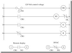
Relays come in all shapes and sizes, from nanorelays to very large relays. Basically a relay is an electrical switch that opens or closes a control circuit. An electromagnetic relay is operated by an electromagnet that opens or closes electrical contacts when power is applied to the electro- magnet. The position of the contacts changes by spring, gravity action, or permanent magnet when the electromagnet is deenergized. Most relays are used in control applications. The contacts are generally in the range of 0 to 35 A. All relays have at least one contact. Relays used in control systems will typically have from one to eight contacts. The contacts can be Normally Open or Normally Closed. Some relays have contacts added or can be changed in the field from open to closed or from closed to open. There are timing relays that are used to control events by time, and there are latching relays that remember their last state. Relays are used to give multiple contacts to an input or pilot device and can extend the control circuit to many different circuits with different voltages or requirements. As you will see in Fig. 3-1, one relay CR1 can control several devices, and the output contacts can control any voltage and current within the range of the relay’s contact specifications.
Shown in Fig. 3-1:
Line 1 Normally Open flow FS1 and control relay CR1. Normally Open flow switch closes and energizes CR1 when the liquid rises to a preset level.
Line 2 Normally Open contact of relay CR1, pump motor starter M1, Normally Closed overload contact of motor starter M1. When CR1 is energized, the contact closes and the pump motor starter is energized. The pump runs until the liquid level drops to a preset level.
Line 3 Normally Open contact of relay CR1, green pilot light. When CR1 is energized, the contact closes and the green pilot light is illu- minated until the liquid level drops to a preset level.
Line 4 Normally Closed contact of relay CR1, red pilot light. When CR1 is energized, the contact opens and the red pilot light is turned off until the liquid levels drop to a preset level.
Output contacts
1. Normally Open contact terminals 3 and 4. When the control relay CR1 is energized, the contact will close and illuminate a remote dis- play until the liquid level drops to a preset level. This control circuit is 24 V DC.
2. Normally Closed contact terminals 5 and 6. When the control relay CR1 is energized, the contact will open and the HVAC control circuit will be opened until the liquid level drops to a preset level. This con- trol circuit is 48 V AC.
Open Frame Relay
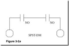
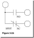
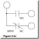
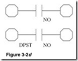
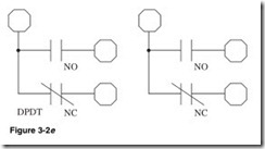
Figure 3-2 is an open frame relay. These relays are used in a dust- proof enclosure or in an environment that has no dust in the air. This relay is available in single-pole single-throw double-make with one Normally Open contact (SPST-NO-DM), single-pole double-throw with one Normally Open contact and one Normally Closed contact (SPDT), double-pole single-throw Normally Open (DPST-NO), and double-pole double-throw (DPDT). Coil voltage is from 24 to 480 V AC. Contacts are rated at 40 A. See Fig. 3-2a, b, c, and d.
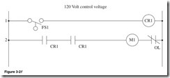
Shown in Fig. 3-2f:
Line 1 Float switch FS1 and control relay CR1. When level reaches a preset amount, the float switch closes and energizes control relay CR1. CR1 remains energized until level drops below a preset amount.
Line 2 Normally Open contact CR1, Normally Open contact CR1, motor starter M1. When CR1 is energized, CR1 contacts close and motor starter M1 is energized; the pump runs until CR1 is deenergized.
Heavy-Duty Industrial Relays
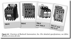
Heavy-duty industrial relays (Fig. 3-3) are electromechanical relays. The coil voltage can be 5 to 600 V AC. These relays are used in con- trol circuits. They have typically from one to eight contacts, which can be any combination of Normally Open and Normally Closed contacts.
Heavy-duty industrial relays can have field-changable contacts. They are available with sealed, reed, or standard contacts, and these contacts can be mixed to meet the field requirements. Contacts are rated from 5 to 35 A. Timer decks are available for some types of these relays. The timer decks extend the function to allow time control.
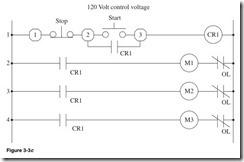
In the circuit in Fig. 3-3c, one three-wire start/stop station is used to control three motors using a control relay.
Shown in Fig. 3-3c:
Line 1 Terminal 1, Normally Closed Stop button, terminal 2. Down one line, Normally Open CR1 contact. Up one line, Normally Open Start button, terminal 3, and control relay CR1. When the Start button is pressed, control relay CR1 is energized, CR1 contacts are closed, and the relay is electrically latched. The control relay CR1 will remain energized until the Stop button is pressed.
Line 2 Normally Open contact of control relay CR1, motor starter M1, and overload contact of motor starter M1. When control relay CR1 is energized, then contact CR1 will close, the starter will be energized, and the motor will run.
Line 3 Normally Open contact of control relay CR1, motor starter M2, and overload contact of motor starter M2. When control relay CR1 is energized, then contact CR1 will close, the starter will be energized, and the motor will run.
Line 4 Normally Open contact of control relay CR1, motor starter M3, and overload contact of motor starter M3. When control relay CR1 is energized, then contact CR1 will close, the starter will be energized, and the motor will run.
Sealed Relay (Ice Cube)
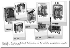
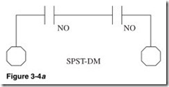
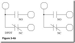
In Fig. 3-4, we see the sealed relay, also known as an ice cube relay. These relays can be socket-based or soldered. They can be base-mounted or flange-mounted. Contacts will vary with the relay selected. This relay has single-pole single-throw double-make with one Normally Open con- tact (SPST-DM-NO), double-pole double-throw (DPDT), and three-pole double-pole double-throw (3PDT), and is available from 24 to 120 V AC and 6 to 24 V DC. Contacts are rated at 20, 25, and 30 A. See Fig. 3-4a, b, and c.
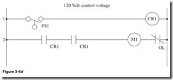
In Fig. 3-4d I use an SPST-DM contact.
Shown in Fig. 3-4d:
Line 1 Float switch FS1 and control relay CR1. When the level reaches a preset amount, the float switch closes and energizes control relay CR1. CR1 remains energized until the level drops below a preset amount.
Line 2 Normally Open contact CR1, Normally Open contact CR1 motor starter M1. When CR1 is energized, then CR1 contacts close, motor starter M1 is energized, and the pump runs until CR1 is deenergized.
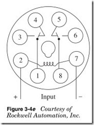
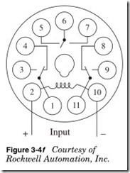
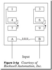
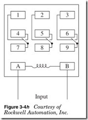
Figure 3-4e, f, g, and h comprises ice cube relay pin outs. These are stan- dard pin outs, but despite all so-called standards, they can change from manufacturer to manufacturer. Most ice cube relays will have the pin outs stamped on the top of the relay. It is a good idea to check the pin outs before connecting the relay. As you can see in the 8-pin relay base in Fig. 3-4e, the coil is pins 2 and 7. On the 11-pin relay in Fig. 3-4f, the coil is pins 2 and 10. The flat blade relays are a little more consistent, as you can see in Fig. 3-4g and h. It is always a good idea to check it out before you hook it up.
Latching Relays
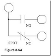
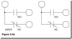
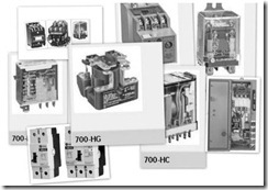
Latching relays are available in many configurations—heavy-duty indus- trial relays, high-current contact relays, and sealed relays also known as ice cube relays. Figure 3-5 shows a mechanical latching relay. The contacts remain in their last state until reset. These relays can have one AC coil or two DC coils. They can be panel-mounted, socket-based, or soldered. This relay has single-pole double-throw with one Normally Open contact and one Normally Closed contact (SPDT), double-pole double-throw (DPDT) with one coil, and double-pole double-throw (DPDT) with dual coils; this relay is available as single-coil AC or dual- coil DC. See Fig. 3-5a and b.
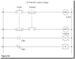
Shown in Fig. 3-5c:
Line 1 Normally Open latch push button, Normally Closed unlatch push button, and CR1 latch coil.
Line 2 Normally Closed latch push button, Normally Open unlatch push button, and CR1 unlatch coil.
Line 3 Normally Open CR1 contact, green pilot light.
Line 4 Normally Closed CR1 contact, red pilot light.
When the latch push button is pressed, it closes the contact in line 1 and latches the relay and opens the contact in line 2 so that the unlatch and latch coils are not energized together. The relay closes the contact in line 3, and the green pilot light is illuminated. The relay opens the contact in line 4 and turns off the red pilot light. The relay will remain latched, even if power is lost, until the unlatch push button is pressed.
When the unlatch push button is pressed, it opens the contact in line 1, so that the unlatch and latch coils are not energized together, and closes the contact in line 2 and unlatches the relay. The relay opens the contact in line 3, and the green pilot light turns off. The relay closes the con- tact in line 4, and the red pilot light is illuminated. The relay will remain unlatched until the latch push button is pressed.




![Figure-3-5-Courtesy-of-Rockwell-Auto[2] Figure-3-5-Courtesy-of-Rockwell-Auto[2]](http://machineryequipmentonline.com/electric-equipment/wp-content/uploads/2020/06/Figure-3-5-Courtesy-of-Rockwell-Auto2_thumb.jpg)
