THERMOSTATS
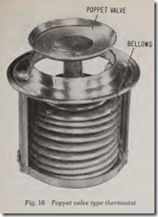
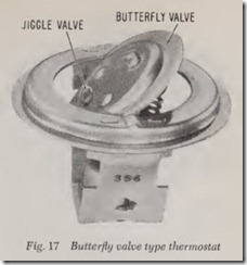
There are two kinds of thermostat valves, the poppet type, Fig. 16, and the butterfly type, Fig.17. Both valves are shown fully open. There are three methods of opening a thermostat valve:
l. By a bellows which contains a volatile liquid whose vapor pressure expands the bellows and pushes th e poppet valve open.
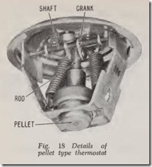
2. By the use of fine crystals (inside a small metal container called a pellet) which expand when heated and thus open the valve with the aid of suitable linkage.
3. By a bi-metal coil which expands when heated and thus opens the valve.
Bellows Type Thermostats
The bellows is partly filled with a liquid which boils at a low temper ature. Before it is filled, the air is pumped out of it. Then the liquid is put in and the bellows is sealed. Consequently, at air temperature there is a vacuum in the bellows which holds the poppet valve closed against its seat. The liquid starts to boil at its opening tem perature-160 degrees for example. As the tem perature rises from this point, the vigor of boiling increases and the vapor pressure goes up until the thermostat is fully open when the temperature has risen 20 to 25 degrees or more.
Pellet Type Thermostat
The powder-like crystals are tightly packed in side the metal pellet, Fig. 18. When they expand they force the rod upward. The rod acts on a crank which rotates the butterfly shaft to open the valve. When they contract the valve is closed by the springs shown, which pull on the valve.
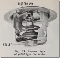
A different butterfly construction is shown in Fig. 19. The valve has no shaft but extensions on the butterfly arc pivoted in holes in the housing. The spring holds the valve closed by the pull of its upper end on a slotted jaw which is riveted to the butterfly. The valve is opened by the pellet rod pushing upward on a piece which is attached to the slotted jaw.
Thermostat Bleed Hole
All thermostats have a small bleed hole (about 1/16″) in the valve to permit the escape of air and bubbles of steam from the water in the system to the top tank of the radiator when the thermostat is closed. These gases are carried through the hole along with a small stream of water. Some thermo stats have a “jiggle valve,” Fig. 17, consisting of a rod in the escape hole. A small weight is hung from the rod. The jiggling of the weight and rod prevents clogging of the hole. Sometimes the bleed hole is located in the radiator outlet.
Thermostat Temperature for Alcohol
If alcohol anti-freeze is used, a thermostat which opens at 160 degrees should be used be cause a thermostat which opens at a higher tern perature will permit the alcohol to boil, especially if the car is driven hard in mild winter weather.
Thermostat Temperature for Heater
The effectiveness of the car heater is propor tional to the coolant temperature. Therefore, a thermostat that opens at a high temperature will keep the car warmer. If the thermostat opens at a higher temperature than 160 degrees, a permanent type antifreeze must be used.
WATER TEMPERATURE CONTROL
In order to explain how the thermostat controls water temperature, let us assume that the cooling system is in normal condition. We also assume that it is designed with enough capacity to operate without over-heating when the air temperature is 100 degrees.
Assume, for example, that the thermostat starts to open at 160 degrees and is fully open at 180 degrees. When the engine is started from cold, the water temperature quickly rises to 160 degrees and the thermostat starts to open. If the weather is very cold, the thermostat will open a little, say to 165 degrees. If it tries to open more, the increased flow of water will cool it off and the thermostat will drop back to the 165-degree position.
Actually, however, a thermostat starting to open at 160 degrees will seek to maintain minimum temperature control subject to the influence of engine heat load and ambient (under hood ) air temperature.
If the car is driven hard on a 100-degree day, the them1ostat is wide open when 180-degree water temperature is reached. Recall that we as sumed that the cooling system was designed for proper cooling at 100 degrees air temperature. If the air temperature is higher than 100 degrees and/ or the cooling system is not in perfect condi tion, the water temperature will rise higher than 180 degrees. The thermostat has no longer any control over the water temperature.
There are two ways of using a thermostat to control water temperature: the choke type and the by-pass type.
Choke Type of Temperature Control
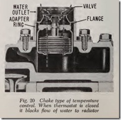
The choke type of temperature control is shown in Fig. 20. When the thermostat is closed, it blocks the flow of water to the radiator. Arrows show flow of water when the thermostat is open. In this picture, it would seem that the body of the thermostat blocks the flow of water even when it is open. But this is not true as Fig. 16 clearly shows.
By-Pass Type of Temperature Control
The by-pass type is illustrated in Fig. 5. When the thermostat is open, water flows as indicated by the black arrows. It enters at the pump inlet, flows to the pump impeller and from thence flows through the cylinder block, and up into the cylin der head. Then it flows forward through the head to the front where it goes upward through the open thermostat valve to the radiator outlet which is connected to the top of the radiator.
When the thermostat is closed, no water can flow through the radiator and, therefore, the pump takes its supply from the cylinder head as shown by the white arrows and discharges it into the block as indicated by the black arrows, Fig. 5. Thus the pump simply circulates the water through the engine until the thermostat opens. When the thermostat opens a little, water still flows to the pump through the small entry passage but the bulk of the water flows out of the very much larger outlet passage and from thence to the radiator.
The by-pass water passage is clearly shown in Fig. 5. When the thermostat is closed, the water pump draws water from the cylinder head (see arrow) and pumps it into the cylinder block through passages not shown; the direction of water flow is indicated by an arrow.
When the thermostat valve is open, the pump draws water from the lower part of the radiator and delivers it to the cylinder block as indicated by the lower arrow. A small amount of water still is circulated through the by-pass passage.
Thermostat Replacement
To remove a thermostat, first remove the water outlet housing (also called the thermostat hous ing) after taking out the flange screws. Remov e the gasket. Inspect the thermostat. Clean gasket surfaces.
Be careful to install the thermostat valve right side up. The bellows or capsule should be on the underside in order to be in contact with the hot water in the cylinder head. Some thermostats are stamped front or top. Be sure to install them this way.
On some by-pass types, there is a rubber gasket above the valve-usually a rubber washer which fits between the top of the thermostat and the housing. If this gasket is not installed, the thermo stat will give no temperature control because the water flows unhindered through the space where the gasket should be. If an upper gasket is re quired, it is packaged with the new thermostat.
When installing a thermostat, coat the gasket surfaces with gasket cement. Use a new gasket. After installing, be sure to tighten the screws snug. Then after the engine has been brought up to normal operating temperature test for leakage.
Selecting a Thermostat
There are several manufacturers of thermostats and all of them make a line of thermostats to fit all cars. The opening temperature of the thermostat is marked on it.
Note that if there is alcohol anti-freeze in the cooling system it is not advisable to use a thermo stat that opens at a higher temperature than 160 degrees because alcohol is likely to be lost, espe cially during warm spells in winter. This may happen even with a pressure cap because of “after boil,” which means that boiling occurs after the engine is stopped.
When a hot engine is shut off, the coolant in the water jackets must cool off the hot engine. The absorption of this heat may cause the alcohol in the water to boil and the pressure created by the boiling may open the pressure cap and alcohol will be lost.
HOSE
Hose for cooling systems and heaters is made with inside diameters of 3/8″, W’, 5/8″, :li”, 1″, HI”, Bi”, 1W’, 1%”, 2″, 2.14″, 2Jf”, 2:Jl”, 3″. The smaller diameter hoses listed are for heater con nections.
There are various types of hose to meet a variety of requirements as follows:
1. Straight hose cut to correct length.
2. Straight hose in three-foot lengths or longer.
It may be used for slight bends.
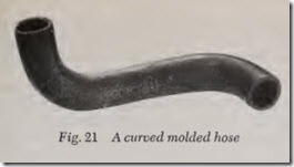
3. Curved molded hose which is made to exact length , Fig. 21.
4. Curved molded hose. A section is cut from the hose to match the old hose removed from the car. This hose is suitable for both upper and lower radiator connections.
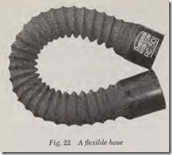
5. Flexible hose, Fig. 22. This type of hose is used to connect the lower tank of the radia tor to the water pump. The water pump causes a suction in this type hose and, when necessary, it is equipped with a wire spring to prevent its col lapse. It can be cut to various lengths so that 12 to 20 sizes will fit most cars.
CORVAIR COOLING SYSTEM
The engine is entirely shrouded with sheet metal pieces that attach directly to the engine and form a plenum chamber-a condition in which the pressure of the air in an enclosed space is greater than that of the outside atmosphere.
A centrifugal blower, mounted to the top of the crankcase cover, spins on a vertical shaft to deliver cooling air outward and downward over the cylin ders and heads. The air then enters a duct under each bank from where it travels rearward to be exhausted at an opening at the rear of the engine.
The rate of engine cooling is regulated by a bellows-type thermostat at the lower part of the plenum. This them1ostat operates a cooling air valve which moves in and out of the eye of the blower to control the air flow. The ring closes the blower air intake until the engine has reached its correct operating temperature. In the event of a failed thermostat bellows, the ring will remain in the open position to prevent overheating of the engine.
The blower, which runs on a sealed, perma nently lubricated ball bearing, is belt-driven by a pulley mounted at the extreme rear end of the crankshaft. A generator drive pulley at the left rear of the engine and an idler pulley at the right rear provide a means of changing belt direction from a vertical plane at the crankshaft pulley to a horizontal plane at the blower pulley.
An oil cooler through which a portion of the air passes before discharge, is mounted above the air exhaust duct near the left rear comer of the engine.
WHEN WATER BOILS
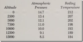
Water boils at 212 degrees at sea level where the atmospheric pressur e is 14.7 pounds per square inch. This pressur e represents the total weight of air resting on each square inch of the earth’s surface. Think of it as a one-square-inch column more than 100 miles high.
Th e air becomes progressiv ely thinner as we go upward. At 10,000 feet ther e are only 10 pounds of air pressure on each squ are inch of the earth’s surface and water boils at 193 degrees. At 15,000 feet, the air pressure is only 8.5 pounds and water boils at 185 degrees.
We may sum up these facts by stating that as pressure is reduced, the boiling point temperature is reduced because it is easier for steam bubbles to form as the pressure is owered.
On the other hand, if pressure is increased beyond 14.7 pounds per square inch, it becomes more difficult for steam bubbles to form and, therefore, it requires a higher temperature to cause boiling.
The table below gives the temperature at which water boils with various radiator pressure caps. If the cap leaks, the boiling point is 212 degrees.
| Pressure | Boiling Temperature |
| 0 | 212 |
| 4 | 224 |
| 7 | 232 |
| 9 | 237 |
| 13 | 246 |
| 14 |
249 |
The effect of altitude on atmospheric pressure and boiling temperature is shown in the table below.
What Pressure Cap Does
Under normal conditions the pressure in the cooling system will be maintained at the pressure which is stamped on th e pressure cap. However, when overheating occurs, instead of the water boiling at 212 degrees as it would without a pressure cap, it does not boil until it reaches the temperature given in the table above.
This is a very desirable advantage because it often happens that faults in the cooling system might be just enough to cause boiling at 212 degrees but not enough to boil the water at some higher temperature. And it should also be realized that the higher the water temperature , the greater is the quantity of heat that the air absorbs, since the rate of absorption is proportional to the differ ence in temperature between the surrounding air and the water.
For example, if the air temperature is 100 de grees and the water temperature is 212 degrees, the difference is 112 degrees. With a 13-pounds pressure cap the water boils at 246 degrees; the temperature differ ence is 146 degrees, and the gain in cooling ability is 146/112 or nearly 30 per cent.
A pressure cap is of great value if something goes wrong with the cooling system at high alti tude. For example, at 5000 feet, water boils at 202 degrees but with a 4-pound cap it cannot boil until the cooling water reaches 224 degrees.
The preceding remarks may have implied that pressure caps make cars less prone to overheating than cars made years ago. This is not quite true.
Radiators today are smaller than they used to be because a new model is styled without much regard as to how much space is needed under the hood for the machinery. Consequently, in many cases the engineering department has been up against it to find enough room for a radiator of adequate size. At the same time, fancy grilles have interfered with the Bow of air to the radiator.
Pressure caps are the answer to the problem be cause they permit the water to rise beyond 212 degrees without boiling.
Because of modern styling, today’s cars are likely to overheat in slow stop-and-go traffic driv ing in hot weather even though they will not overheat when driven at top speed when the atmospheric temperature is 100 degrees. The ex planation is that one way to obtain satisfactory cooling capacity on the open road is to circulate the water much faster. This means that water pump pressure must be greatly increased.
Overheating in Traffic
The principal causes of overheating in traffic are ( 1) the inefficiency of centrifugal water pumps at low rpm; ( 2) smaller radiator frontal areas; ( 3) more underhood obstructions due to engine shape and accessory installations which create higher underhood temperatures and back pressures, and ( 4) torque converter heat loads which appre ciably contribute to low speed stop and go over heating in hot wea ther.
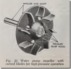
The older type “low speed” engine water pump had an impeller with straight radial blades which had ample pumping capacity for idling and very low speed, as well as for higher speeds. To make a high volume pump for the modern high speed engine the impeller blades are curved, Fig. 23. Such an impeller can be designed for maximum efficiency at any desired pump speed or engine speed and at this speed it is much more efficient than the straight-blade pump. However, since its efficiency falls off rapidly when the pump is run at lower (or higher) speeds, modern pumps have greater cross-sectional area both at the intake and outlet, and thereby compensate for the curved shape of the impeller.
