Digital Noise Generation—Chain Code Generators
The binary sequence generated by a chain code generator appears to have no logical pattern; it is, to all intents and purposes, a random sequence of binary numbers. The code is generated by a shift register that is clocked at a predetermined frequency and whose input is derived from a network that develops a function of the outputs from the register.
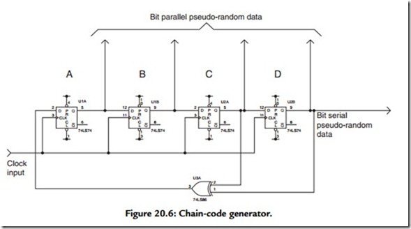
A basic form of chain code generator is illustrated in Figure 20.6, which consists of a 4-bit shift register whose input is derived from the output of an exclusive-OR gate, itself fed from the penultimate and last output of the shift register. The output from the chain
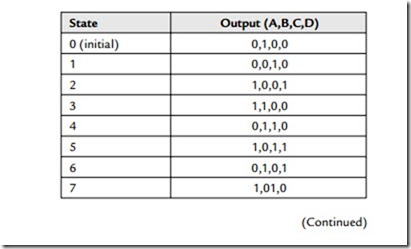
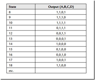
code generator may be taken in serial form (from any of the data-latch outputs) or in parallel form (from all the data latch outputs). In operation, imagine that the output of stage B starts with a 1 as power is applied, but that all the other outputs start with a 0. Note that the output of the XOR gate will only equal 1 when its inputs are of a different state (i.e., nonidentical). We can now predict the ensuing pattern that results as the shift register is clocked:
Note that, at state 15, the pattern starts to repeat. This sequence is known as the maximum-length sequence. The fact that the outputs states are predictable illustrates that the output of the code generator is not really random at all but is a pseudo-random binary sequence (PRBS). The sequence does, however, have some very “random” qualities—like a very nearly equal number of 1 s and 0 s (think of it a coin-tossing machine)! Practically, this lack of true randomness does not matter provided that the sequence is long enough to appear random in any particular application. In every case of an n-stage, chain code generator, the longest (maximal length) sequence of 1 s and 0 s repeats after (2 e n – 1) states. Note that, as illustrated in Figure 20.6, a pathological condition can occur if all outputs power up in an identical 0 state—in which case 0 s will propagate indefinitely around the chain code generator, resulting in no output. Practical circuits have to include provision to prevent this situation from ever occurring. Indeed it is precisely because of the necessity to avoid this “forbidden” all zeros state that the output of the chain code generator illustrated in Figure 20.6 consists of a cycle of 15 (rather than the more intuitively expected 16) states.
It can be shown mathematically that the output binary sequence from the chain code generator has a frequency spectrum extending from the repeat frequency of the entire sequence up to the clock frequency and beyond. The noise is effectively flat (within 0.1 dB) to about 0.12 of the clock frequency (Fc). The noise source is –3 dB at 0.44 Fc and falls off rapidly after that. For most applications (audio included), simple low-pass filtering of the digital maximal-length sequence results in white Gaussian noise, provided that the breakpoint of the low-pass filter is well below the clock frequency of the register (say 0.05 Fc to 0.1 Fc), that is, in the region where the spectrum of the digital noise is constant. The analogue filter may be a simple 6-dB/octave RC circuit, but usually a sharper active filter is desirable.


