Protection that is provided by the thermal device can be reduced by temperature variations. Ambient temperature affects the trip time of all thermal devices. If the ambient temperature is IO O F, the device may not trip soon enough to protect the motor.
Thermal protective devices are mounted either inside the motor or in its connection box.
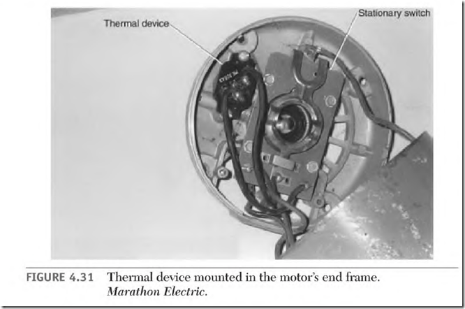
When the device is mounted inside (Fig. 4.31), the motor’s internal temperature is factored into the thermal device’s trip temperature. The trip temperature is based on the motor having reached full running temperature.
If the motor is overheated, it may trip off each time the motor tries to start. The cycle will continue until the motor is disconnected long enough for both to cool. If the motor is extremely cold, the thermal device may not trip before the windings are damaged.
Frequent starts can cause excessive tripping with an internally mounted thermal device. High ambient temperature may trip off a lightly loaded motor when it is restarted.
If the thermal device is mounted in the connection box, the motor’s internal temperature won’t affect it.
Alternative Start-Winding Switches
The stationary switch and centrifugal device assembly can be replaced with numerous types of start-winding controls, which include:
• Potential relay start switch
• Electronic start switch
• Time-delay electronic start switch
• Heat-activated start switch
• Current relay start switch
Potential Relay Start Switch
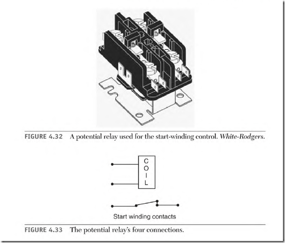
The potential relay start switch is shown in Fig. 4.32. A motor’s original stationary switch contacts and centrifugal device can be replaced with a potential relay. They are available for 115- and 230-volt applications. The same switch can control two-, four-, and six-pole capacitor-start motors.
Potential Relay Components
The potential relay start switch illustration in Fig. 4.33 consists of a coil and a set of horsepower-rated contacts. The coil must match the voltage applied
to the motor (115 or 230 volts). A dual-voltage motor requires a coil rated for a Il 5-volt application.
The relay contacts must be rated as high as or higher than the motor’s horsepower. Some large capacitor-start motors have a two-circuit start winding and use a separate relay for each circuit.
Operation of the Potential Relay
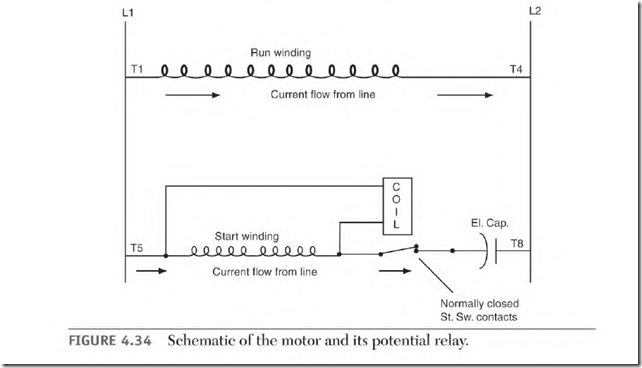
Figure 4.34 is a schematic of the motor and its potential relay. The power factor of the start winding is low when the motor is starting. As the rotor accelerates, the voltage/ current angle (timing), or power factor, of the start winding improves. As the power factor improves, the voltage transformed from the rotor poles to the start winding increases. At 75 to 80 percent of synchronous speed, the voltage across the start winding is high enough to
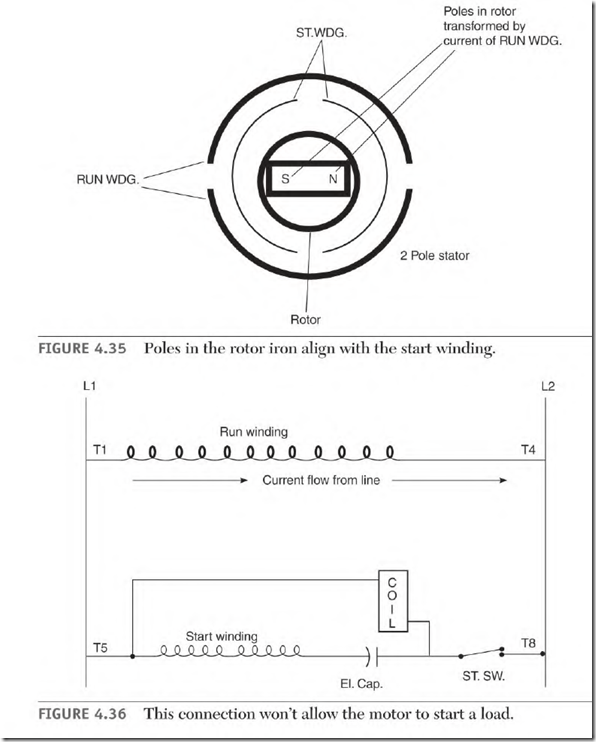
make the relay coil function. The start winding is now disconnected from the line. Power continues to be transformed into the start winding from the rotor, keeping the contacts open until the motor is shut off. (A voltage is transformed into the start-winding coils from the poles of the rotor.) Figure
4.35 shows the alignment of rotor poles.
The voltage value (at 75 to 80 percent of synchronous speed) varies slightly from motor to motor. Spring tension (which holds the contacts closed) can be adjusted to fit a motor’s individual requirement. Increasing or decreasing the spring tension is done by bending the spring support.
If the motor’s capacitor is connected in the relay coil/ start-winding circuit, the power factor is immediately raised, and the relay coil functions too soon (Fig. 4.36). When the contacts open, the rotor speed is so slow that the run winding can’t pull the rotor up to speed.
If the motor is extremely overloaded, or if there is a short power interruption, the potential relay reconnects the start winding and brings the rotor back up to disconnect speed. (Overload protection should disconnect the motor before its windings are damaged by an overload.)
Coasting Load Problem with Potential Relay
A coasting (or flywheel type) load will generate power in the motor’s circuitry. As the motor coasts, the magnetized rotor, the stator windings, and
the capacitor(s) change the motor into a static generator. Generated power (within the windings) will cause the potential relay to open and close the switch contacts several times before the motor stops.
When the motor is shut off, the relay coil allows the start contacts to close.
With the contacts closed, the run winding provides a closed circuit, which allows the amperes to flow. Amperes (flowing in the run winding) create poles in the rotor cage that magnetize the rotor iron. Current flow through the rotor cage transforms a voltage into the start winding. The transformed voltage (helped by the discharging capacitor current) in the start winding is high enough to open the contacts again. This cycling will continue until the speed no longer produces enough voltage to make the relay coil function.
There is excessive wear on the relay’s contact assembly when the contacts cycle on and off. Figure 4.37 shows a connection that will eliminate this problem. When the start winding is isolated by this connection, the capacitor doesn’t discharge into the closed circuit of the stator windings and there is no contact cycling. A 15,000-ohm, 2-watt bleeder resistor should be installed across the capacitor to discharge it, when the motor is idle. The resistor alone will not keep the switch from cycling.


