Holley Carburetors
ONE-BARREL CARBURETORS
Models 1904, 1908, 1960
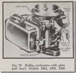
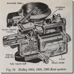
These carburetors, Fig. 75, are single barrel units with a single venturi. It is a compact unit less than two-thirds as high as carburetors of standard design having a comparable capacity. In reducing its height the conventional air horn has been eliminated and the choke plate is placed in the venturi. In addition to its normal function, the choke plate, when open, aids in the distribution and vaporization of the fuel discharged by the main nozzle. Fig. 76 illustrates the float system. The fuel, under pressure from the engine’s fuel pump, enters the carburetor through the float needle valve.
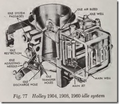
Fig. 77 shows the idle system. The air and fuel travel down a passage under the air bleed and through the idle passages to the idle discharge holes.
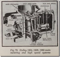
Fig. 78 pictures the main metering and power systems. During part throttle operation (main metering system) a supply of air is introduced into the main fuel well by the high speed air bleed. The fuel and air travel up the main well and are then discharged into the venturi where the fuel vaporizes and mixes with the air flowing through the carburetor.
The power system vacumn diaphragm and spring are actuated by the vacuum below the throttle plate. The diaphragm and spring are held in the “up” position which allows the valve to remain closed until the vacuum drops to approxi mately 6 to 7 inches of mercury. Under load, as when climbing hills, the vacuum drops because it is necessary to open the throttle wider in order to maintain speed. When the vacuum drops below 6.5 inches of mercury, the power valve is opened by the spring and held open by the diaphragm rod. Additional fuel then flows through the power valve, into the main well and out the main dis charge nozzle.
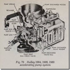
The accelerating pump system is shown in Fig.79. Fuel is drawn into the pump chamber, through the pump inlet passage and the pump inlet ball check valve on the upward stroke of the pump diaphragm. When the throttle is opened, the diaphragm is moved on its discharge stroke, thus closing the pump check valve and overcom ing the weight of the pump discharge needle valve. The accelerating fuel then goes around this valve and out the pump discharge nozzle.
The manually-operated choke functions in the same manner as previous Holley carburetors with out automatic choke.
Model1909
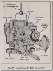
This carburetor, Fig. 80, consists of two main sub-assemblies: the air horn and the main body.
The air horn acts as a cover and includes the fuel inlet system and the automatic choke mech_anism. The main body includes the fuel bowl, the fuel metering systems, the throttle shaft and plate, and the spark control valve.
The carburetor has the conventional five fuel metering systems to provide the correct fuel-air mixture for all phases of engine operation. An anti stall dashpot, for cars equipped with automatic transmission, is attached to the carburetor and controls the closing rate of the throttle plate.
Model1920
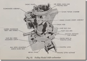
In this carburetor, Fig. 81, fuel from the bowl flows into four basic fuel metering systems which are: the idle system, the main metering system, the power system and the accelerating pump sys tem. The choke valve, located in the bore of the carburetor, is connected to a well-type automatic choke.
Additional fuel for acceleration is supplied by a diaphragm type, mechanically operated pump. The pump is operated by a cam connected by linkage to the throttle shaft. An override spring on the pump insures a prolonged discharge of fuel for smoother operation.
A power valve, mounted in the metering body and actuated by manifold vacuum, delivers the additional fuel necessary for full power and high speed operation.
The fuel bowl is vented by an external vent valve located in the top of the bowl. The vent valve is connected by linkage to the throttle shaft so that the valve is opened a prescribed distance when the vehicle is at idle or completely shut down.
Some models of this carburetor are equipped with a spring staged choke. This choke, Fig. 81, is a device incorporated in the choke mechanism which reduces the choke plate clo§ing torque when cranking the engine at temperatures below zero. Thus the spring staging of the choke is a better match for the engine’s starting mixture requirements at both low and moderate tem peratures.
Model1931
This carburetor features a one piece main body casting along witl1 a large capacity fuel bowl. The fuel inlet and float assembly located in the center of the fuel bowl cover maintains a stable fuel level for best performance on turns. The large capacity fuel bowl is designed to efficiently handle fuel vapors.
The automatic choke is contained in a housing which is an integral part of the carburetor body.
The carburetor metering systems are similar to the Model1904 and 1908 discussed previously.
TWO & FOUR BARREL CARBS
Models 2300, 4150,4160
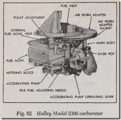
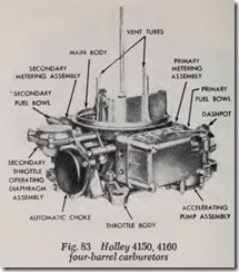
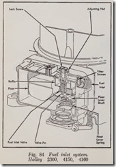
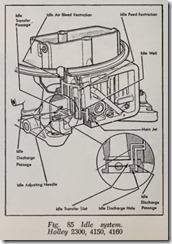
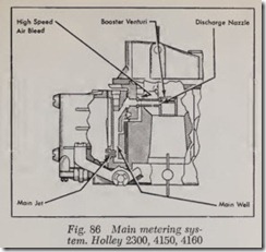
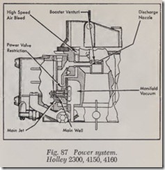
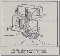
Model 2300 is a two-barrel carburetor, Fig. 82, while models 4150 and 4160 are four-barrel units of the same basic design as the two-barrel unit, Fig. 83. The two primary bores of both type carburetors supply the fuel-air mixture throughout the entire range of operation for all four basic fuel metering systems as well as the fuel inlet system, Figs. 84 to 88. The two secondary bores of the four-barrel carburetors function only when speed or load requires them. Each barrel has its own venturi, idle system, main metering system, booster venturi and throttle plate.
In the secondary system of four-barrel units, at lower speeds the secondary throttle plates remain nearly closed. When engine speed increases to a point where additional breathing capacity is needed, the vacuum controlled secondary throttle plates open automatically.
The secondary fuel bowl is equipped with a fuel inlet valve which regulates the flow of fuel into the bowl-the same as the primary fuel bowl. The three secondary fuel systems are the transfer system, main metering system and by-pass system, Figs. 89 and 90.
The transfer system begins to function when the secondary throttle plates begin to open. At this point the fuel flows through the secondary main jets int the idle passages which are similar to those in the primary metering body.
When the secondary throttle plates are opened further the pressure differential causes the secon dary main metering system to begin functioning.
When manifold vacuum drops to a pre-deter mined value, the secondary power valve opens, thus allowing a full mixture to be discharged in the secondary booster venturi as the secondary throttle plates are opened. These three secondary systems provide a smooth transition of power instead of a sudden surge.
