Introduction
HOW COOLING SYSTEM WORKS
The purpose of the cooling system is to prevent temperatures of cylinders , pistons, valves and other engine parts from rising high enough to destroy them or to destroy the oil which lubricates them.
The cylinder bores and cylinder head are surrounded by water passages called water jackets. The water pump draws water from the bottom of the radiator and sends it through the water jackets in the cylinder block, then up into the cylinder head from whence it is delivered to the top tank of the radiator. The water is cooled as it flows down through the radiator passages by air flowing through the core, impelled by both the fan and the forward motion of the car.
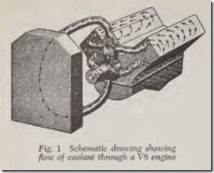
Fig. 1 shows schematically how the coolant circulates through the system in a V8 engine. The coolant is drawn from the bottom of the radiator by the water pump and delivered to both cylinder blocks simultaneously. The coolant circulates around the cylinders and up through drilled holes to the cylinder heads. After circulating throu gh the heads, the coolant flows through the ther mostat housing (also called water manifold ) which is located at the top of the water pump.
To sum it up: Water cools the engine and air cools the water. Anything which prevents this water -air system from working properly will cause overheating.
The liquid in the cooling system may be either water or a mixture of water and anti-freeze. The term “coolant” is commonly used to describe both of them.
New cars are equipped at the factory with a thermostat that is designed to open at 180 to 200 degrees. Therefore, maximum water temperature will not exceed 5 degrees above the designed opening temperature of the thermostat.
In other words, cooling temperature never ex ceeds these figures unless the cooling system is below par or unless the car is driven at high speed and/or the atmospheric air temperature is more than 100 degrees.
Fig. 2 illustrates a typical cooling system. Ar rows show the direction of water flow. The water pump and fan are mounted on opposite ends of the same shaft. A pulley attached to the fan hub is driven by a fan belt connected to a pulley on the front end of the crankshaft.
The water inlet passage at the top of the radia tor is connected to the cylinder head by rubber hose. Likewise the water outlet passage from the lower radiator tank is connected to the pump by rubber hose.A thermostat valve in the cylinder head is automatically closed when the engine is cold and open when the engine is warm.
When closed, it prevents flow of water through the radiator. Therefore, th e heat of combustion quickly warms the water in the water jackets to normal operating temperatur e. Not until then does the thermostat start to open and permit flow of water to the radiator. Th erefore, the engine warms up in minimum time. The thermostat keeps the cooling system at normal temperature in cold weather, as will be explained later.
The cylinder head is bolted to the cylinder block. The joint between head and block is sealed by a cylinder head gasket which prevents leakage of water and combustion gases. There is a series of holes which permit flow of water from block to head, Figs. 2 and 3.
WATER PUMP
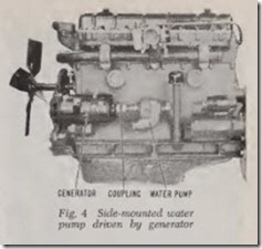
The water pump is mounted on the front end of the cylinder block, Fig. 2, except on Rambler InLine engines up to 1956, which have the pump on the side, Fig. 4. When the pump is placed at the front of the cylinder block, the front end of the pump shaft is used to drive the fan on most cars.
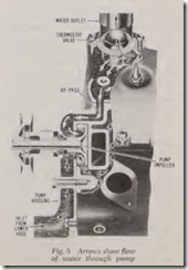
The water pump is always a centrifugal type. The rotation of the impeller blades, Fig. 5, throws the water radially outward by the action of cen-· trifugal force, delivering the water to the pump discharge openings at considerable pressure. At the same time, suction is created at the pump intake to draw water from the bottom of the radiator.
FAN
A fan usually consists of four blades, occasion ally more, bolted together with a drive pulley to a hub. Ordinarily, this hub is mounted on the water pump drive shaft, the fan belt driving both the pump and the fan. Drive pulley and fan blades can be removed without disturbing the water pump. On some models a variable speed fan drive system is incorporated with the fan drive.
Variable Speed Fans
The fan drive clutch, Fig. 6, is a fluid coupling containing silicone oil. Fan speed is regulated by the torque-carrying capacity of the silicone oil.
The m ore silicone oil in the coupling the greater the fan speed, and the less silicone oil the slower the fan speed.
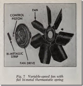
Two types of fan drive clutches are in use. On one, Fig. 7, a bi-metallic strip and control piston on the front of the fluid coupling regulates the amount of silicon oil entering the coupling. The bi-metallic strip bows outward with a decrease in surrounding temperature and allows a piston to move outward. The piston opens a valve regulat ing the flow of silicone oil into the coupling from a reserve chamber. The silicone oil is returned to the reserve chamber through bleed hole when the valve is cloed.
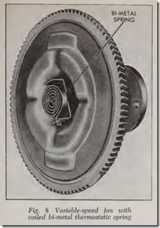
On the other type of fan drive clutch, Fig. 8, a heat-sensitive, bi-metal spring connected to an opening plate brings about a similar result. Both units cause the fan speed to increase with a rise in temperature and to decrease as the temperature goes down.
In some cases a Flex-Fan is used instead of a Fan Drive Clutch. Flexible blades vary the vol ume of air being drawn through the radiator, automatically increasing the pitch at low engine speeds.
Fan Drive Clutch Test
Run the engine at a fast idle speed ( 1000 rpm) until normal operating temperature is reached. This process can be speeded up by blocking off the front of the radiator with cardboard. Regard less of temperatures, the unit must be operated for at least five minutes immediately before being tested.
Stop the engine and, using a glove or a cloth to protect the hand, immediately check the effort re quired to turn the fan. If considerable effort is required, it can be assumed that the coupling is operating satisfactorily. If very little effort is re quired to turn the fan, it is an indication that the coupling is not operating properly and should be replaced.
Service Procedure
CAUTION: When it becomes necessary to remove a fan clutch of the silicone fluid type, Fig. 7, the assembly must be supported in the vertical (on car) position to prevent leaks of silicone fluid from the clutch mechanism. This loss of fluid will render th e fan clutch inoperative.
The removal procedure for either type of fan clutch assembly is generally the same for all cars. Merely unfasten the unit from the water pump and remove the assembly from the car.
The type of unit shown in Fig. 7 may be par tially disassembled for inspection and cleaning. Take off the capscrews that hold the assembly together and separate the fan from the drive clutch. Next remove the metal strip on the front by pushing one end of it toward the fan clutch body so it clears the retaining bracket. Then push the strip to the side so that its opposite end will spring out of place. Now remove the small control piston underneath it.
Check the piston for free movement of the coupling device. If the piston sticks, clean it with emery cloth. If the bi-metal strip is damaged, re place the entire unit. These strips are not inter changeable.
When reassembling, install the control piston so that the projection on the end of it will contact the metal strip. Then install the metal strip with any identification numerals or letters facing the clutch. After reassembly, clean the clutch drive with a cloth soaked in solvent. Avoid dipping the clutch assembly in any type of liquid. Install the as sembly in the reverse order of removal.
The coil spring type of fan clutch cannot be disassembled, serviced or repaired. If it does not function properly it must be replaced with a new unit.
WATER DISTRIBUTING TUBE
On some engines a water distributing tube is inserted in the water jacket (see Fig. 3). The front end of the tube receives the water directly from the pump. Holes in the tube discharge jets of water to provide extra cooling for the exhaust valve seats and valve stems.
RADIATOR
There are two types of radiators presently in use. The first is the downflow variety in which the coolant moves vertically from top to bottom. The other type is the crossflow in which liquid move ment is from one side of the radiator to the other. Heat transfer from the coolant to the outside air takes place in the radiator core which consists of many vertical or horizontal passages which termi nat e on either end in tanks. Downflow systems have two tanks, at the top and bottom of the core while the crossflow radiator has its tanks mounted on the sides, at left and right. On the crossflow,
water inlet is still at the top of one of the side tanks and it exits at the bottom of the other side tank.
The various parts of the radiator are soldered together. The components are made of copper or brass, in preference to other metals, because of their high heat conductivity , ease of soldering, and resistance to corrosion. In recent years aluminum has been used to some extent for this pur pose. Regardless of the met als used, radiator cores are of two general types, tubular and cellular.
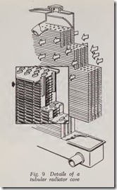
The radiator core, Fig. 9, . consists of tubes to which thin copper or brass fins are soldered in order greatly to increase the radiating surf ace. The tubes may be round, or Battened as shown.
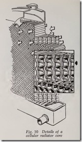
In the cellular core, Fig. 10, the water passages and air fins are made by soldering preformed sheets of thin copper or brass as shown. The wa ter passages are about 1/16″ wide.
The top tank of the radiator is equipped with a baffie which distributes the water over the top of the radiator core so that all the radiator passages are fully supplied.
DRAIN COCKS & PLUGS
There is dways a drain cock at the bottom of the radiator and there may be one or more drain cocks in the cylinder block to drain the water out of the water jackets. Screw plugs are sometimes used instead of drain cocks, especially in the cylinder block.
RADIATOR CAPS
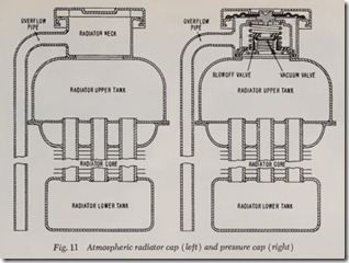
In t he left view of Fig. 11 is illustrated a radiator cap which permits the cooling system to operate under atmospheric air pressure since th.e overflow pipe is open to th e atmosphere. There IS slow but constant evaporation of water. Water may also be lost through the overflow pipe whe ever the bra kes are applied with full force. This results in a high surge of water in the top tank when som e of it escapes through the overflow pipe. Th e overflow pip e, in spite of its fa lts, is n essential p art of th e cooling system. Without It, the radiator or hose conn ections would burst whene ver th e cooling system boils. Bursting would occur whenever the r adiator were com pletely filled with water. La ter, when .the .w ter was heated, expansion would create an Irresistible pressure.
RADIATOR PRESSURE CAP
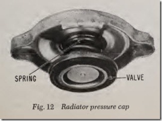
Pressure caps are standard equipment on all cars ma de in th e past several years. The cap, Fig.12, has a spring closed valve which opens at some designated point above atmospheric pressure. Each make and model car have cooling systems designed to operate at a certain pressure above atmospheric and caps are supplied for this specific pressure. There are, therefore, caps available with pressure ratings ranging in steps from 4 to 19 pounds. Thus equipped, water coolant in these systems has its boiling temperature raised from 225 for the 4 pound caps to 257 degrees for the 19 pound systems. In the range under con sideration, every pound of pressure put on the cooling system by means of the pressure cap raises the boiling temperature about 2.5 degrees.
Actual pressure required to open a certain rated cap may vary slightly. So if a pressure cap de signed to open at 14 pounds in fact opens at anything between 13 and 15 pounds it is ac ceptable.
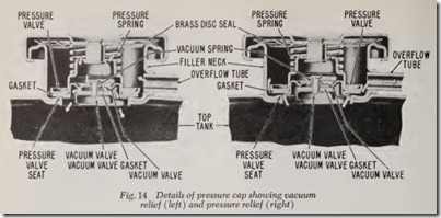
Fig. 13 shows a pressure cap and filler neckwhile Fig. 14 illustrates the details of a typical cap. In the left picture the large coil spring seals the pressure valve and its rubber gasket tight against its seat in the filler neck. The picture at the right shows that pressure in the cooling system has opened the pressure valve, allowing discharge of steam and water through the overflow pipe as indicated by the white arrows. Note that the top edge of the filler neck is sealed by a springy brass disc attached to the cap.
If the coolant boils, there will be a rapid condensation of steam when the engine is shut off and, in consequence, several inches of vacuum may be created within the cooling system. As a result, the end tanks could be crushed inward. To avoid this possibility, all pressure caps are equipped with a small vacuum valve, one type is shown in Fig. 14. The picture at left shows this vacuum valve open with atmospheric air Bowing into the system by way of the overflow pipe as indicated by the white arrows. When there is no vacuum in the radiator, the valve is closed by the small coil spring shown. Another type of vacuum relief valve has a weighted end that keeps the cap, and thus the system, vented to the atmosphere most of the time. It is only when the pressure builds up in the radiator that the valve is forced closed.
Closed Cooling Systems
So-called closed cooling systems are arranged like conventional systems except that they have an additional expansion tank. Usually connected to the inlet tank of the radiator, the expansion tank provides reserve cooling capacity and reserve ex pansion space. Generally attached to the radiator by means of a conventional radiator hose, Fig. 2, it is located at the highest point in the system. When such a closed system is installed, the pressure cap is placed on the expansion tank and the radiator itself has no cap. The place where it would ordinarily be is taken up by the tube leading to the expansion tank.
If the coolant boils, instead of simply leaving the system via the radiator cap and overflow pipe it can expand in the extra tank and, if the boiling is not severe, it will be cooled there and no liquid will be lost from the system. It is thus especially useful in cases of “afterboiling” such as occur when the engine is turned off immediately after a hard run. Under such circumstances the cooling system can not dissipate the accumulated heat rapidly enough and it will boil slightly for a short time. If severe boiling occurs in a closed system, due to some malfunction, the pressure cap will open just as it would in an ordinary system and coolant will be lost.
In another variation of the closed cooling sys tem, the expansion tank, called in this case an overflow tank, is connected to a conventional radiator having a plain cap by means of a vent tube. Serving exactly the same function as the previous tank, the overflow unit can be located at any level in the system except the lowest point and is equipped, as before, with a pressure cap. Coolant is added through the regular filler neck and if it boils the radiator simply overflows into the extra tank. On cooling down, the system syphons the liquid back from the overflow tank.
