Control of Motor Starting
Control circuits and equipment can perform varied functions. These can be grouped into 11 general types according to the effect they have on the motor to be controlled. Each of the general types can be broken down into endless variations, but they each stem from a few basic principles which, if understood, are the key to control work. It is the aim of this chapter to present these principles in as nontechnical a language as possible .
2 ·1 MOTOR STARTING
There are several general factors to be considered in the selection of motor-starting equipment. The most obvious of these are the current, voltage, and frequency of the motor and control circuits. Motors require protection according to the type of service, the type of motor, and the control functions that will be needed.
Whether to use a full-voltage starter or a reduced-voltage starter may depend on the current-carrying capacity of the plant wiring and the power company lines and rates. Other factors, such as the need for jogging or inching, acceleration control, or the type of motor to be used, will also affect this selection.
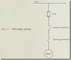
Full-voltage Starting. The requirement of this type of starting is simply that the motor leads and line leads be connected (Fig. 2 ·1). This could be accomplished merely by using a knifeblade switch, but this method would provide no protection for the motor except the circuit fusing.
For small fractional-horsepower motors on low-amperage cir cuits, the simple switch may be satisfactory and is used frequently. Many appliances use nothing more than the cord and plug as the disconnecting means, with a small toggle switch to start and stop the motor. Because the motor is not discon nected from the line on power failure, this type of starting con trol can be an advantage for fans and other devices that other wise would have to be restarted.
For motors up to 10 horsepower (hp) and not over 600 volts, the manual across-the-line motor starter may be used to give manual control. Most of these units give overload protection and undervoltage release.
The most popular starter for motors up to 600 hp and 600 volts or less is the magnetic across-the-line starter. This starter, combined with pilot devices, can give full protection to the motor and fully automatic operation.
The vast majority of motors today are built to withstand the surge of current that occurs when they are suddenly thrown across the line. Not all our plant circuits can stand this surge, however, nor can all the power company equipment. When a large motor starts at full voltage, it may cause a voltage drop large enough to drop out other control equipment. Should the voltage drop be serious enough, it might even cause a dimming of lights in other buildings.
In most industrial installations the utility company penalizes , in the form of higher rates, for surges of excessive current on the line by the use of a demand meter. The demand meter regis ters the maximum average demand of power on the line for a given period of time, generally a 15-minute period. This factor should always be taken into consideration when the method of starting large motors is being decided. The extra cost of power because of the excessive demand for starting large motors across the line may well exceed the cost of reduced voltage starting, which would materially reduce the demand reading.
When considering using full-voltage starting, always check the building wiring and distribution system capacity. Should the wiring be inadequate, either it must be increased in capacity or reduced-voltage starting must be used.
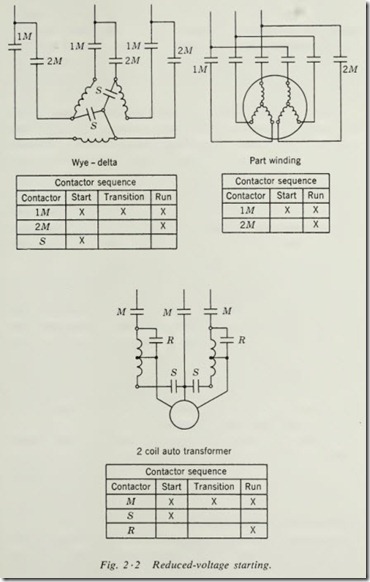
Reduced-voltage Starting. Whenever the starting of a motor at full voltage would cause serious voltage dips on the power company lines or the plant wiring, reduced-voltage starting be comes almost a necessity (Fig. 2 ·2). There are, however, other reasons for using this type of control. The effect on the equip ment must be taken into account in the selection of motor
starters. When a large motor is started across the line, it puts a tremendous strain or shock on such things as gears, fan blades, pulleys, and couplings. Where the load is heavy and it is hard to bring it up to speed, reduced-voltage starting may be neces sary. Belt drives on heavy loads are apt to have excessive slip page unless the torque is applied slowly and evenly until full speed is reached.
Reduced-voltage starting is accomplished by the use of resistors, autotransformers, or reactors in order to reduce the line voltage to the desired value during starting. Many electronic devices are also used to reduce starting current and starting torque. Regardless of the means of reducing the voltage, it must be designed to fit the particular motor to be started. It is not within the scope of this book to go into the design of reduced voltage starters, but rather to point out the need for proper selection according to the specifications furnished by the motor manufacturer.
Another method of achieving reduced-voltage starting is to use a wound-rotor motor with secondary control (Fig. 1 ·2). With this system, a full-voltage starter is used on the primary or stator winding, and resistance grids are put in series with the secondary or rotor winding to reduce torque and starting current. The secondary control device shorts out the resistance grids as needed for acceleration, until at full speed all the resist ance is shorted out and the motor runs as a squirrel-cage motor. The advantage of secondary control is that it gives speed control as well as reducing the starting current.
Regardless of the method used to provide reduced-voltage starting, it must be kept in mind that the starting torque of the motor is also reduced. If a motor is not capable of starting its load under across-the-line conditions, the application of re duced-voltage starting will only aggravate the situation because of the reduced starting torque. The torque of an induction motor is a function of the square of the rotor current, or approximately the square of the line current. If the starting voltage is reduced by 50 percent, the motor current will be reduced to 50 percent of normal, but the torque will be reduced to 25 percent of normal.
Some of the methods of obtaining reduced-voltage starting will result in very little or no acceleration under starting condi tions. This requires that the total acceleration occur after full voltage has been applied. The starting current during reduced voltage conditions will be somewhat less than across-the-line starting current. When full voltage is applied, however, the start ing current will be approximately the same as it would have been if the motor had been placed across the line in the begin ning. This type of starting is generally referred to as increment starting and is used generally to spread the rate of change of current demanded from the line over a longer period of time. Part-winding squirrel-cage motor starting and wye-delta starting of squirrel-cage motors generally fall in the increment-start cate gory (Fig. 2·2).
Jogging and Inching. Printing presses , cranes, hoists, and sim ilar equipment require that the motor be started repeatedly for short periods of time in order to bring some part of the machine into a given position. This process is known as jogging or inch ing. Even though these terms are often used interchangeably, there is a slight difference in their meaning. If the motor is started with full power in short jabs, it is jogging. If the motor is started at reduced speed so as to let the machine creep to the desired spot, then it is inching.
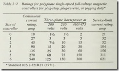
When jogging service is required, the starter must be derated.
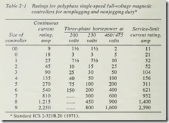
For instance, a size 3 starter rated at 30-hp 230-volt three-phase · normal duty should be derated to 20 hp for jogging duty. The manufacturer’s literature should be consulted for ratings of start ers in jogging service. The standards shown in Tables 2 ·1 and 2 ·2 have been set up by NEMA (National Electrical Manufac turers Association).
2 ·2 ACCELERATION CONTROL
Squirrel-cage motors do not generally lend themselves very well to speed or acceleration control. There are special types of squir rel-cage motors designed for two-, three-, or four-speed applications. This type of multispeed squirrel-cage motor does not have a true variable speed but rather has several definite speeds which may be used as desired or in steps. When adjustable speed is required, the wound-rotor motor with secondary control or the adjustable-speed a-c commutator motor is probably the most practical.
Manual control of acceleration or speed may be accomplished with multispeed squirrel-cage motors by having the operator close the proper contactor as determined by the load or speed requirements. With wou.nd-rotor motors, the secondary or drum controller is moved as needed to give the desired speed.
Automatic control of acceleration may be accomplished by several methods. Probably the simplest is definite-time control. With this method, a time-delay relay is used for each step or speed. When the motor is started in its lowest speed, the first time-delay relay is energized. When this relay times out, it ener gizes the second contactor, increasing the speed to its second step. This process may be carried through as many steps as necessary to give the speed and acceleration desired. The chief disadvantage of this method is that it is not affected by the conditions of the machine, its load, or the motor current.
For machines or equipment that cannot stand full torque until the load has reached a given speed, the system called current limit control should be used to accelerate the motor. In this system each step is brought in by a current relay which will not close the circuit for its speed until the current has dropped to a safe value. The current, of course, will not drop until the motor and the load are running at nearly the same speed. This system is very well suited for belt or gear drives with heavy high-inertia loads . This method of control must be designed for the particular application, and the relays must be set for the particular machine and its requirements. For this reason, they are not available as standard stock controllers.
Another system of acceleration control is slip-frequency control. This system is used on wound-rotor motors and is also used to energize the field of synchronous motors.
Because the secondary voltage and frequency of wound-rotor motors is inversely proportional to the speed, a frequency-sensi tive relay may be used to energize each progressive step or speed. One disadvantage to slip-frequency control is that it must be started on the first, or lowest, speed.
Several features must be kept in mind when selecting the method of acceleration control. Manual control is sensitive only to the operator’s reaction. Definite-time control is sensitive only to the lapse of time. Current-limit control is sensitive to the load on the motor. Slip-frequency control is sensitive to the speed of the motor.
It is quite possible that under certain specific applications a combination of any two or more of the above-mentioned con trol systems might be used to enable the motor to be sensitive to more than one of these factors. Such a controller would of necessity be custom-built to meet the specific requirements of a given installation.
2 ·3 STARTING MULTISPEED SQUIRREL-CAGE MOTORS
Single-speed squirrel-cage motors are generally started by the use of across-the-line magnetic starters. A multispeed squirrel cage motor, however, requires a controller that is built for its par ticular windings.
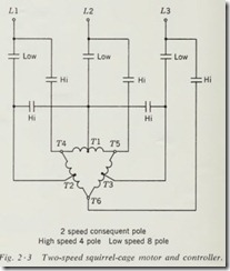
Two-speed motors may either have two separate stator wind ings or be of the consequent-pole type (Fig. 2 ·3) which have only one stator winding. The two speeds are obtained with the consequent-pole motor by regrouping the coils to give a different number of effective poles in the stator. It is characteristic of this type of motor that it gives a 2 to 1 speed ratio. Three-speed motors usually have one winding for one speed and a second winding that is regrouped to give the other two speeds. Four speed motors usually are wound with two windings which are regrouped to give two speeds each. The number of contactors, the order in which they close, and the number and types of overload units required depend on the method of obtaining the various speeds.
2·4 STARTING WOUND-ROTOR MOTORS
The wound-rotor motor is essentially the same as a squirrel-cage motor except that it has definite windings instead of short-cir cuited bars on the rotor. By the introduction of resistance in series with the rotor windings, with a drum controller or with contactors, the speed may be controlled in any number of steps. The most common method of starting wound-rotor motors is by the use of a manual or magnetic full-voltage starter on th.! primary, interlocked to the secondary controller (Fig. 2 ·4). The secondary controller may be a manual drum controller, a motor driven drum controller, a liquid rheostat, or a magnetic con tractor designed for secondary control. The secondary controller may be for starting service only and have only two or three steps, or it may be for speed control as well and have any number of · steps.
It is necessary that there be an interlock between the primary and secondary controllers that will prevent the motor from start ing without all the resistance in the secondary circuit unless the motor and the machine are designed to start at any speed.
