inductors
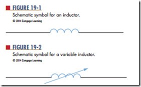
Inductors are devices designed to have a specific inductance. They consist of a conductor coiled around a core and are classified by the type of core material— magnetic or nonmagnetic. Figure 19-1 shows the symbol used for inductors.
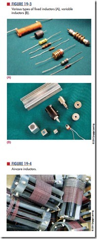
Inductors can also be fixed or variable. Figure 19-2 shows the symbol for a variable inductor. Variable inductors are created with adjustable core material. Figure 19-3 shows several types of inductors used for adjusting the core material. Maximum inductance occurs when the core material is in line with the coil of the wire.
air–core inductors, or inductors without core material, are used for up to 5 millihenries of inductance. They are wrapped on a ceramic or phenolic core (Figure 19-4).
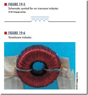
ferrite-core inductors and powdered iron cores inductors are used for up to 200 millihenries. The symbol used for an iron-core inductor is shown in Figure 19-5. An iron-core inductor is also referred to as a choke. Chokes are used in DC and low-frequency AC applications.
toroid-core inductors are donut-shaped and offer a high inductance for a small size (Figure 19-6). The magnetic field is contained within the core.
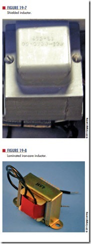
shielded inductors have a shield made of magnetic material to protect them from the influence of other magnetic fields (Figure 19-7).
laminated iron-core inductors are used for all large inductors (Figure 19-8). These inductors vary from 0.1 to 100 henries, the inductance depending on the amount of current flowing through the inductor. These inductors are sometimes referred to as chokes. They are used in the filtering circuits of power sup- plies to remove AC components from the DC output. They will be discussed further later on.
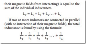
Inductors typically have tolerances of 610%, but tolerances of less than 1% are available. Inductors, like resistors, can be connected in series, parallel, or series- parallel combinations. The total inductance of several inductors connected in series (separated to prevent
Questions
1. What are inductors?
2. Draw the symbols used to represent fixed and variable inductors.
3. What is another name for a laminated iron- core inductor?
4. What are the formulas for determining total inductance in
a. Series circuits?
b. Parallel circuits?
What is the total inductance of a circuit with three inductors, 10 H, 3.5 H, and 6 H, con- nected in parallel?
