MICROPHONES
In practically all modern acoustical work, the oscillations in sound pressure are picked up by some form of receiving electroacoustic transducer, such as a microphone, which converts them into similar electrical current or voltage oscillations. The latter either may be electrically amplified for immediate reconversion into sound energy or stored in some form, such as on a magnetic tape.
When operating in air such transducers are known as microphones, and when operating in water as hydrophones. Microphones are used for converting music or speech into electrical signals which are transmitted or processed and then reproduced. They serve as measuring instruments, converting acoustical energy into electrical currents which actuate indicating meters.
MICROPHONE
All sound recording starts with the use of microphones. Professional recording engineers use microphones in large number, with the output from each microphone being separately recorded on a wide strip of recording tape. For example, 32 or more microphones are used to record a large orchestra. The placing of each microphone, the amplitude of recording from each microphone, and the subsequent mixing of the sound from each track to form two tracks of a stereo recording or four tracks of a discrete quad recording are operations which require great skill and experience.
A microphone is a device of the class called transducers which converts sound waves in air into electrical waves of the same frequency and shape. In the process of conversion, the microphone must make use of either the pressure of the air waves, or the velocity at which the air moves. So, we have two types of microphones, the pressure-operated types, and the velocity-operated types.
CHARACTERISTICS OF MICROPHONES
There are many types of microphones available. Each has certain advantages and disadvantages. The choice of a microphone depends upon the type of material to be reproduced, the placement of the microphone, whether it is to be used indoors or outdoors, the frequency response desired, and a number of other factors.
The basic types of microphones, grouped according to their principle of operation are : carbon, crystal, dynamic, ribbon and capacitor.
Each of these has its own characteristics with respect to : (1) output level, (2) frequency response, (3) output impedance and (4) directivity. These characteristics ultimately determine the particular type of microphone suitable for a given application.
Output Level
The output level of a microphone governs the amount of amplification that must be available for use with the microphone. The output level of microphones is usually given in dB preceded by a minus sign. The minus sign means that the output level is so many dB below the reference level of 1 milliwatt for a specified sound pressure.
The unit of sound pressure used for rating microphones is referred to as a bar. A bar is equal to a sound pressure of 1 dyne per square centimetre. Speech provides sound pressures between 0.4 and 15 bars. For music the pressure ranges from 0.5 bars to 1250 bars.
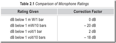
Microphones are rated in a number of different ways, and this often causes confusion. If ratings are given in any manner other than in bars, it is a good idea to convert their output level rating to dB below 1 milliwatt for a sound pressure of 1 bar (see Table 2.1).
A microphone with a low output level necessitates the use of an amplifier with greater gain, which, in turn increases the possibility of noise and hum.
Frequency Response
The frequency response of a microphone is a rating of the fidelity of relative output voltage which results from sound waves of different frequencies. The simplest way to find a complete picture of the frequency response characteristics of a microphone is to plot a curve of its output voltage vs input frequency. Since good modern microphones are relatively flat over their range, it is often considered sufficient to specify the range over which their output does not vary more than plus or minus 1 or 2 dB.
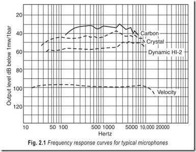
For ordinary home high-fidelity use, a microphone frequency-response curve should be reasonably flat between 40 and 10,000 Hz. With systems designed specifically for speech reinforcement, a lower limit of 150 Hz and an upper limit of 5,000 Hz is entirely satisfactory. Where it is desired to reproduce music with the highest possible fidelity, the frequency response should be flat (within 2 dB) from about 40 to 15,000 Hz, Fig. 2.1 shows the response of several types of microphones.
Output Impedance
A microphone, like any other component with electrical inputs or outputs, has a value of impedance. When a microphone is connected to an amplifier, a complete circuit is formed and electric current flows whenever a sound causes the microphone to generate an electrical voltage.
For most high quality microphones impedance is low, a few ohms ranging up to a hundred ohms or so, but as little as a fraction of an ohm in a ribbon microphone. Only capacitor and ceramic crystal microphones have high impedances.
The importance of microphone impedance is not a matter of the precise value but of the ability of the microphone and the recorder to be matched together. High impedance microphones must be connected into a recorder with high impedance input, otherwise both the signal amplitude and the frequency range will be adversely affected.
In general, when a ceramic or capacitor microphone is connected to a low impedance amplifier input, the output from the amplifier is small and the lower frequencies are reduced disproportionately, producing an unpleasant shrill sound on playback. Cassette recorders of good quality are not as a rule designed to take high impedance microphones, except when such microphones are supplied with the recorder, and if, for any reason, such microphones are used, a high impedance preamplifier must be used between the microphones and the recorder.
Low impedance microphones and inputs are much more common; one good reason is the hum problem. The frequency of the supply voltage, 50 Hz, is, like any other ac signal, radiated from any wire on which it is present, and can also be picked up on any wire. You can prove this for yourself by touching the input of an amplifier with the volume control turned half-way up. The resulting amplified hum sounds very loud in the loudspeakers, showing that the hum signal must be at least as strong as the signals normally fed into the amplifier. Radiation through the air at this low frequency is not an efficient process, however, as the house wiring is not long enough to act as an efficient antenna (aerial), and the hum signal picked up on a piece of wire behaves as if it had come from a high impedance source. If the input of the cassette recorder amplifier is at high impedance, then the whole hum signal can be transferred to it unless every piece of wire and every connector is efficiently shielded from the hum by earthed metal casings. If, on the other hand, the input to the cassette recorder amplifier is at low impedance, the hum signal, if picked up, is greatly reduced in amplitude even if no screening is used.
Directivity
Microphones do not respond equally to sound reaching them from all directions. Their frequency response characteristics also vary, depen+ding on the angle at which the sound reaches them. A microphone may respond equally to all frequencies between 40 and 10,000 Hz when the sound is originating directly in front of it, while the high-frequency response falls off rapidly as the sound originates further to either side. Where it is necessary to pick up sound from all directions, the directional characteristics of all microphones are not suitable.
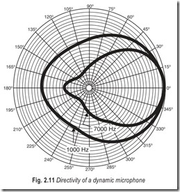
The way in which a microphone responds to sounds coming from different directions is plotted on a circular graph which is known as a polar diagram. The centre of the circle is the zero point and concentric circles indicate successively higher levels of response as they move outward. The top of the circle is the front and the bottom the back of the microphones, and the straight lines radiating from the centre denote the corresponding angles.
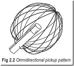
A true omnidirectional microphone would have a plot of a perfect circle, Fig. 2.2, hence there would be little point in making a diagram. Few manufacturers in fact publish polar diagrams of such instruments. Actually, the pickup is rather less at the rear than at the front, so the plot would have a smaller radius at the bottom than at the front. An omnidirectional microphone is most commonly used for general recording, and is the best for recording sound sources that move about a lot.
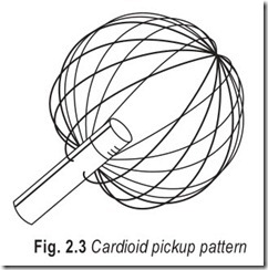
When the directional response of a pressure gradient microphone is plotted, the shape of the figure is something like a heart, with the maximum response in the front, curving around the sides to a minimum near the rear. Therefore, it is termed cardioid (Greek, kardia = heart), Fig. 2.3.
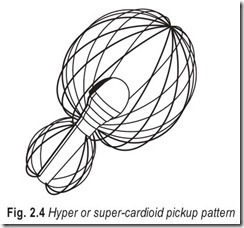
To achieve a greater rejection of sounds coming from the sides, the vents in some models are designed to admit a higher sound pressure to give more cancellation at the rear of the cone or diaphragm. The result can be seen in the polar diagram, Fig. 2.4, as a narrower forward lobe, and the response is known as hyper or supercardioid. One effect of this is that rear sounds can actually exert more pressure on the back of the cone than on the front, so movement is produced, although it is negative, that is, a high pressure region produces forward instead of backward movement of the cone.
This appears on the diagram as a small lobe sometimes marked with a negative sign at the rear or below the centre position. It means that there is some pickup at the rear although not so much as at the front, but the point of minimum pickup is nearly always about 120° from the front. The rear lobe varies considerably with frequency and is sometimes found with cardioid as well as the hypercardioid.
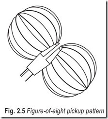
If both sides of the ribbon of a velocity microphone are open to free air, it follows that sounds from front or back will have exactly the same effect. In fact, there is no front or back. As the ribbon is actuated by particle velocity instead of pressure, it responds only when facing the sound source. Sounds coming from the sides exert equal force on both sides of the ribbon and so have no effect. It is, therefore, bidirectional, and its diagram consists of two near circular lobes looking like a figure 8, hence the designation of a figure of eight response, Fig. 2.5.
Example 2.1 : The voltage gain of an amplifier, when it feeds a resistive load of 1.0 kW, is 40 dB. Determine the magnitude of the output signal voltage and the signal power in the load when the input signal is 10 mV.
Example 2.2 Express the power dissipated in a 15 W resistor in decibel relative to 1 mW when the voltage across the resistor is 1.5 V rms.
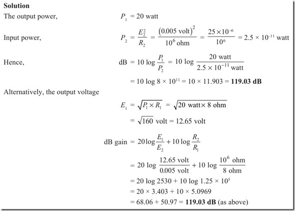
Example 2.3 An audio amplifier produces 20 watt output across an 8 ohm resistance when a 5 millivolt signal is applied to its input across a 1 mega ohm resistor. Determine the decibel gain.
If the resistance ratio ![]() had been ignored, an erroneous gain figure of about 68 dB would have been obtained.
had been ignored, an erroneous gain figure of about 68 dB would have been obtained.
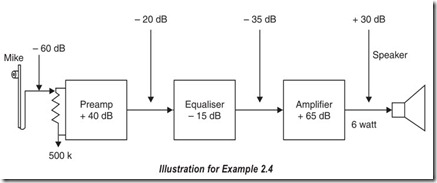
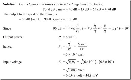
Example 2.4 A microphone has an output of – 60 dB (with respect to a zero level of 6 milliwatt) and is connected to the 0.5 mega ohm input of a preamplifier. The preamplifier has a gain of + 40 dB. The signal then passes through an equaliser with an insertion loss of – 15 dB and through a main amplifier with a gain of + 65 dB. If the output to the speaker is 6 watt, find the total power gain and the input voltage to the preamplifier.
CARBON MICROPHONES
For a telephone system important requirements are (i) the microphone shall be of convenient size; (ii) capable of mass production at low cost while possessing high sensitivity to operate from a simple battery; (iii) its performance must be stable and adequate to provide intelligible speech and articulation and; (iv) it need not necessarily include the higher harmonic frequencies for reproducing.
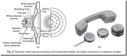
On the other hand, microphones used for purposes such as radio broadcasting are relatively few in number and their cost is not a primary consideration: high fidelity reproduction up to about 10,000 Hz for natural speech and music transmission is essential.An inset pattern of carbon granule microphone is in general use for telephone systems: the usual type is a self-contained and sealed microphone which can be readily and completely removed from the telephone instrument. Its operation depends upon the variation in contact resistance of the carbon granules when they are subjected to the pressure changes of sound waves. It follows that this type of microphone does not produce an emf but functions by modulating the current obtained from an external battery.
The essential components of this microphone are two electrodes and carbon granules which are loosely packed in between the electrodes. One electrode is fixed relative to the other which carries a diaphragm to respond to the pressure changes of the sound waves. Movements of this diaphragm vary the resistance of the granules and so control the line current in accordance with the sound waves reaching the diaphragm. An increase in pressure produces a reduction in resistance and an increase in current. The elementary circuit arrangement is shown in Fig. 2.6. Constructional details of
the inset carbon microphone are shown in Fig. 2.7.
The carbon microphone generates a continuous hiss. This hiss is due to small variations in contact resistance which take place between the carbon granules.
With carbon microphones the electrical output is not directly proportional to the sound input level. The practical effect of this non-linear distortion is to produce harmonics of the lower speech frequencies and these harmonics tend to mask higher frequencies normally present in the speech, resulting in loss of clarity or articulation.
The average output level of carbon microphone is of the order of –30 dB (see Fig. 2.1). The best carbon microphones have a frequency response of approximately 60 to 7,000 Hz. They are substantially non- directional although their high frequency response above 300 Hz usually falls off at angles exceeding 40 degrees from the front of the microphone.
When the maximum output level is required from a microphone, the carbon microphone is often used. The frequency response characteristics of the carbon microphone are poor and cannot be used for high- fidelity work.
CRYSTAL MICROPHONES
Certain crystals, such as rochelle salt and quartz possess the property of generating small emf’s when subject to stress or strain. This effect is utilised in what is known as the crystal microphone.
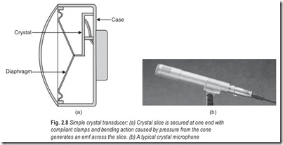
The construction of a crystal microphone is shown in Fig. 2.8. A thin finger shaped slice of crystal is secured at one end by means of a compliant clamp, and the apex of a cone is made to bear against the other. Sound pressure waves cause the cone to alternately press against and bend the crystal slice and release it. Thus, corresponding voltages are generated across the slice. A pair of contacts is fixed to opposite surfaces to take off the signal.
An improvement is obtained if the single slice of crystal is replaced by two slices cemented together. Then, when pressure is exerted, one slice is compressed while the other is stretched. Thus equal and opposite voltages are produced which, being in series like the cells of a car battery, give double the output. Any non- linearity which may arise due to the different mechanical strains between pressure and release is also thereby compensated. The double crystal unit is termed as bimorph.
One of the snags with this type of transducer is the mass which must be moved by the sound pressure acting on the cone. This consists of the mass of the cone plus that of the crystal, or that part of it which is moved. This restricts the frequency response to its upper end to around 10 kHz and also limits the transient response. In addition there are resonances due to the cone and the crystal.
With some of the better microphones the cone does not actuate the crystal directly but through a cantilever. According to the dimensions involved, the effect of the mass of the crystal and the mechanical resistance offered by its stiffness can be reduced but at the same time so also is the amplitude of the transmitted vibrations, hence the signal output.
Another type of construction is the sound cell where several crystal elements are sealed together, this also being termed as multimorph. Here the cone is often dispensed with, the sound pressure waves acting directly on the crystal. Output is lower with this arrangement, but the frequency response is better and also the cone resonance is eliminated.
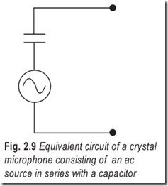
There is no dc path through a crystal microphone, the crystal being an insulator. Having the two electrical contacts on either side of the slice, the unit behaves as a capacitor. The equivalent circuit, then, consists of a voltage source in series with a capacitor, Fig. 2.9. Capacitance values vary, but around 1,000 pF (0.001µF) is typical. This should be taken into account when considering cable requirements.
The crystal microphone is the type most widely used in lower cost installations. It has a relatively high output level and a high impedance. A long cable will reduce the output voltage available from a crystal microphone and may affect its high frequency response.
The output level of this type of microphone is usually between – 48 dB and –60 dB. Their output impedance is almost always more than 100,000 ohms.
Good units may have a frequency response substantially flat between 50 and 10,000 Hz. Units are also available with slightly wider frequency response ranges.
The crystal microphone is normally non-directional although a pressure-gradient crystal microphone which gives a unidirectional response pattern is also being marketed. This microphone gives excellent results.
The natural crystals, such as rochelle salt, are not very durable. They are adversely affected by humidity and high temperature; also they fracture easily when subjected to shock. If a crystal microphone is subjected to a temperature of 130 degrees, it will be rendered completely useless. Care must always be taken to avoid exposing a crystal microphone to direct sunlight for any length of time.
MOVING COIL (DYNAMIC) MICROPHONES
We now come to one of the most common type of transducers, the principle being used both for microphones and loudspeakers.
This type of microphone [Fig. 2.10(a)] works on the generator principle. The diaphragm carries a coil of wire placed in an intense magnetic field of constant value (B). Movements of the diaphragm, consequent upon sound pressure changes, result in an emf (E µ Blv) being generated in the conductor. This emf is proportional to the velocity of motion (v) of the conductor in the air-gap: if the microphone is to have the same sensitivity at all frequencies it is necessary for the velocity of motion of the coil, due to a sound of given intensity, to be independent of the pitch of the sound.
The ends of the coil are secured to two points on the cone and from these a pair of loose flexible wires is connected to terminal tags to which the microphone cable may be connected. So the electrical replica or signal as it is termed, can be conveyed to an external circuit.
In order to respond to transients and high frequency sound waves it is necessary to keep the mass of the cone and its coil as small as possible. For this reason, the coil is usually wound with aluminium wire of very fine gauge and the number of turns is limited. This means that the generated voltage is also limited, and so the natural impedance of the instrument is low. The average is around 30 W, but many models have a transformer incorporated in the instrument itself to give an output at a higher impedance.
Even with these measures, the combined mass of the cone, which must be rigid to faithfully respond to the pressure waves and also keep the coil accuratelycentred within the pole-pieces, restricts transient response and more seriously places the mechanical resonance well within the frequency range of the instrument.
The moving-coil unit is reliable and robust, features which fit it for applications calling for hard usage. It can be made quite cheaply and therefore fills the need for an inexpensive microphone, but refinements and careful design can add considerably to the cost, and so the better units are quite expensive.
The output level of most dynamic microphones is about 55 or more dB below 1 milliwatt per bar. The ordinary dynamic microphone is essentially nondirectional, although its high-frequency response falls off rapidly on either side as shown in Fig. 2.11. To make full use of a dynamic microphone’s frequency range, the microphone should face directly toward the source of sound.
One of the refinements, sometimes found in the better models, is what is known as a hum bucking coil. An ac operated equipment, especially that containing a mains transformer, is often surrounded by a magnetic field which oscillates at the mains supply frequency (50 Hz in India). If a moving coil microphone were used with such a field, a voltage of 50 Hz may be induced into the coil. Although this voltage would be quitesmall so also is that produced by cone movement, hence it could be a significant level as compared to the wanted signal. After amplification the result would be an audible hum. The hum bucking coil is wound in the opposite direction to the moving coil and is positioned close to the moving coil capsule. Any hum field affects both the coils but as they areconnected in series and in opposite phase, it is cancelled by the production of equal and opposite emf.
Moving-coil microphones are often described as dynamic but the term is sometimes applied to all transducers that operate on the electromagnetic principle. Another type is the ribbon unit.
RIBBON (VELOCITY) MICROPHONES
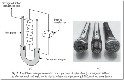
With these microphones, the sound operates the transducing element directly without the use of a cone. A ribbon of aluminium foil, corrugated to allow backward and forward motion, is mounted edgeways between two pole-pieces [Fig. 2.12(a)]. We have here, then, the classic example of electromagnetic generation, a single conductor moving in a powerful magnetic field. There is no multiplication of induced emfs by the successive turns of a coil, the ribbon can be regarded as a coil with but a single turn. As a result, the output voltage is very low and so also is the impedance, something of the order of 0.1W. All ribbon microphones, therefore, have a built-in transformer to step-up the impedance and voltage to a usable level.
Even with the transformer, the output voltage for any given impedance value is still lower than that for a moving coil unit. It depends on the number of magnetic lines of force cut by the ribbon, which in turn depends on the strength of the magnet and the length of the ribbon. To achieve sufficient output, older microphones used large magnets and long ribbons which not only made them bulky and heavy but introduced ribbon resonances well within the audible range of frequencies.
More recent developments have produced materials that enable magnets to be made powerful yet light and also flared front apertures that increase the acoustic force acting on the ribbon. This has enabled ribbon and magnet size to be reduced and units with an adequate output are now available with ribbon sizes less than 1 inch in length and with a mass of less than half a milligram. This has enabled an even smoother and extended frequency response to be obtained with freedom from resonance The output level of a velocity microphone is usually 60 dB below 1 milliwatt per bar. Generally ribbon microphones have excellent response characteristics.
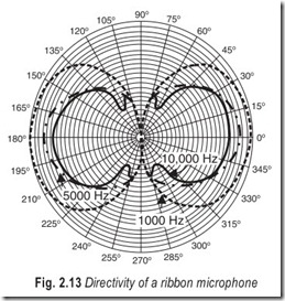
The ribbon microphone is bidirectional. Maximum response is to sound reaching the front or back of the microphone at a 90-degree angle to the plane of the ribbon faces. It is more directional than the crystal and dynamic microphones, the overall response of the ribbon microphone falls off as the angle of sound reaching it varies from 90 degrees to the faces of the ribbon (Fig. 2.13).
The ribbon microphone is quite sensitive to the movement of the air surrounding it, and it must be carefully protected from puffs of wind when used outdoors. A ribbon microphone should be placed at least 18 inches from the source of the sound.
CAPACITOR MICROPHONES
A capacitor (or to give it its original name, condenser) microphone, Fig. 2.14, is one that depends for its operation on the variation of capacitance between a fixed plate and a tightly stretched metal diaphragm. Its development represents a milestone in the history of modern electroacoustics and for a number of years this type of microphone was the accepted standard for high-quality sound systems.
In this case the movable plate is the diaphragm which serves as the sound pressure sensing element. In order that it will respond well to transient and high frequency sound waves, the diaphragm is made very light by forming it from a thin film of plastic material coated with a fine layer of metal. Aluminium is sometimes used for its lightness, but gold is also used for anticorrosion properties in the more expensive instruments. The diaphragm is sometimes embossed with a pattern of shallow troughs, which by varying the depth, width, and number can be made to possess any degree of elasticity. Thus areas of stress are also reduced.
The fixed plate is mounted rigidly behind the diaphragm, and, in order to achieve as high a capacitance as possible very close to it. Capacitance can vary from 5–75 pF, but between 20–30 pF is most common.
There must be adequate passage of air behind the diaphragm, if the microphone is to work as a pressure-gradient transducer, so the whole area of the diaphragm cannot be mated with a corresponding
area of backplate, while with others the plate is of lesser diameter than the diaphragm, thus giving an air gap around its edge. These passages open into the air chamber behind the fixed plate and from there through an acoustic-resistance element to the side vents.
For the capacitor microphone to function a voltage must be applied across it, and this also has the effect of pulling the diaphragm back towards the fixed plate by means of electrostatic attraction. Thus it is kept taut and rigid, a necessary characteristic if it is to respond faithfully to the incoming pressure waves, yet without any penalty in the form of increased mass.
The total capacitance of the unit is small, and therefore, the capacitance variations are minute. In order to produce current flows of usable proportions, the applied voltage must be high. In some cases it can be over 100 V, but around 50 V is common. Some models are designed to work well down to 9 V, and thus receive power from a standard radio battery. These will work with even lower voltages but the sensitivity tends to fall off.
Different voltages will give rise to different diaphragm tensions and sensitivities. As the acoustic resistance in the rear access passage is fixed in value, it follows that any such diaphragm variation will produce a difference in the way it responds to a pressure gradient between front and back. Thus the polar diagram will be modified. Some models make use of this principle to achieve a wide choice of polar diagrams with the same microphone, ranging from omnidirectional, through figure-of-eight and cardioid to hypercardioid merely by altering the polarising voltage.
To conclude, the output level of the capacitor microphone is extremely low, and a high-gain amplifier must be used with it. The amplifier should be mounted directly at the microphone, usually right in the microphone case. The capacitor microphone has very excellent frequency response and low distortion. Because of the necessity of mounting an amplifier at or in the microphone case, the capacitor microphone is not recommended for ordinary high-fidelity (hi-fi) work.
ELECTRET MICROPHONES
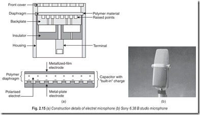
In electret microphones, Fig. 2.15, a permanent electrostatic charge is implanted into the metallised diaphragm, thereby eliminating the need of an external high-voltage source.
One way of doing this is to put the diaphragm sheet between the plates of an air-spaced capacitor which is then charged upto a high voltage. The sheet is then heated and allowed to cool with the charge still maintained across it. When it is removed, it has a permanent static charge which is the equivalent of an applied voltage of around 100 V. This may be considered on par with a permanent magnet which retains its magnetism after the energising field has been removed.
Any electrostatic charge will slowly leak away due to the fact that there is no material yet known that is a perfect insulator. The charge in the diaphragm will gradually diminish and also the effectiveness of the microphone. Its life is measured like that of radioactive substances, as time taken to fall to half its previous level, the half-life as it is usually termed. The makers of electret microphones claim an expected half-life of between 100 to 1000 years, so users need have no worries on that score! Conditions of high humidity though, may well accelerate the deterioration.
A self-contained amplifier is still necessary because the output impedance is of a similar order to that of the conventional capacitor microphones. This can be powered from a small battery cell. As the current taken by the amplifier is very low, just a fraction of a milliamp, it will have an average life of several thousand hours. This is in contrast to the battery life of capacitor microphones using dc converters to supply the polarising voltage which is in the lower hundreds.
Since their introduction, electret units have become very popular as they give reproduction approaching that of the conventional capacitor microphone but without the expense and complication of the external power unit. Most of the built-in microphones fitted to cassette recorders are of this type.
GUN MICROPHONES
The necessity of having a microphone within a short distance of the sound source can in some cases be an inconvenience. In particular, with film and television work, it is essential that the microphone is out of camera range, but there are many other applications where it is not possible to get very near to the source of sound.
An ordinary microphone will pick up sounds from quite a long distance, although the electrical output will be small because of the square law reduction of sound intensity. This in itself is no great drawback as extra gain can be provided in the amplifier. The real problem is that unwanted sounds, which normally would be so weak as to pass unnoticed, now assume a significant proportion compared to the required sound. The extra amplifier gain used increases them too. When operating outdoors this means that distant traffic, aircraft, dogs barking, wind noise and other such sounds become obtrusive, while indoors reverberation from walls and ceiling becomes greater in proportion to the direct sound, so giving an indistinct, distant effect.
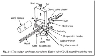
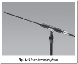
For some while, professional engineers have been using the gun microphone, which is also known as the rifle and barrel microphone. Sounds coming from all directions other than the one to which it is pointing are eliminated. Two types of construction can be used, and both make use of the interference principle.
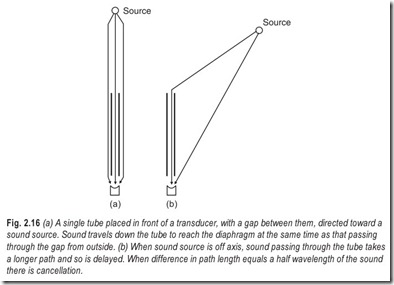
Let us first of all imagine a single tube mounted in front of a pressure microphone but with a gap between the diaphragm and the end of the tube. Sound coming from the direction of the tube axis will pass down the tube and reach the diaphragm simultaneously with the pressure wave that arrives from outside the tube through the gap [(Fig. 2.16(a)]. These will reinforce each other and so will actuate the diaphragm.
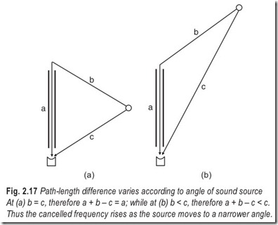
Consider now a sound coming from a point well off axis [(Fig. 2.16 (b)]. It follows two paths, one direct through the gap and the other indirect through the tube. The latter is longer and so the sound wave following this path arrives later. The difference in length between the two paths is equal to the length of the tube in the case of a sound source at right angles to the tube axis, but is less for any angle smaller than a right angle (see Fig. 2.17).
When this difference is equal to half the wavelength of the sound, there will be half-cycle delay between the waves following the two paths; the compression part of one will coincide with the rarefaction part of the other. Thus they will be exactly out of phase and will cancel each other. The result is therefore zero pressure on the diaphragm.
This cancellation occurs when the length difference is half a wavelength and so also at ![]() wavelengths and so on. However, this can be true only when each successive sound wave is identical to its predecessors, such as in the case of a pure tone. Natural sounds are rarely like this as there are constant changes of wave shape and intensity, and so cancellation beyond more than a cycle or two will not occur. In practice, the half and perhaps
wavelengths and so on. However, this can be true only when each successive sound wave is identical to its predecessors, such as in the case of a pure tone. Natural sounds are rarely like this as there are constant changes of wave shape and intensity, and so cancellation beyond more than a cycle or two will not occur. In practice, the half and perhaps ![]() wavelength can only be expected to suffer cancellation. As the path difference varies according to the angle of the sound source from the tube axis, the exact frequencies also vary.
wavelength can only be expected to suffer cancellation. As the path difference varies according to the angle of the sound source from the tube axis, the exact frequencies also vary.
The advantage of gun microphone is to cut down sounds coming from directions other than the desired one, which means that the wanted sound is greater in proportion to the unwanted one, but it is not actually greater enough to be picked up by any other microphone.
Parabolic Reflector
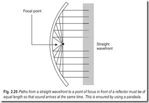
A device which magnifies sound levels acoustically is the parabolic reflector. It works in a very similar manner to the way a concave mirror reflects light, but with additional complications. If a large concave surface is placed in the path of a sound pressure wave, the wave will be reflected and the direction of reflection will be governed by the angle of incidence between the wave and the surface.
In the case of a parabolic surface, the reflection from the whole surface area will converge on a single point which, as in the case of light, is termed the focal point. Thus the pressure is concentrated to a much higher intensity here. A microphone is mounted facing inward to the reflector, with its cone or diaphragm at the focal point, so that most of the sound reaching it is reflected from the parabola.
LAVALIER MICROPHONES
For many applications mobility is a primary requirement for a microphone. Gun microphones have some advantage over those permanently mounted on a stand as they can be used in the hand and carried around to the limit of the connecting cable length. As these can also be fitted to a stand with quick release clips, they have a versatility to which no doubt is due the popularity of this type of instrument.
A disadvantage is that one hand of the user is always occupied and held up in an unnatural position. This can impose a serious restriction on speakers or lecturers who may wish to demonstrate points with models or exhibits, use a blackboard or just be free to use gestures.
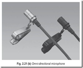
One answer to these problems is the lavalier microphone, which is a small transducer suspended on the chest by means of a cord around the neck.
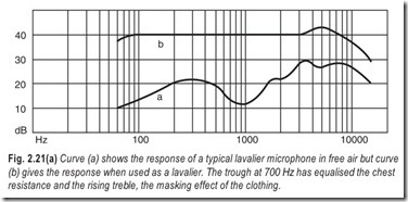
Any type of instrument can be used for the purpose by arranging suitable fittings to take the cord. There are problems involved in using a microphone in this way. One of these is the resonance of the human chest cavity which emphasizes frequencies around 700 Hz and results in an unnatural boominess. Another is the masking effect of clothing which tends to absorb frequencies between 3 kHz and 10 kHz and give a muffled reproduction.
In order to overcome these effects special microphones have been developed for lavalier use. These have a dip in their response around 700 Hz and a rise from 3 kHz upward. These characteristics balance the deficiencies and result in a more or less flat overall response. The frequency curve in free air and that when used as a lavalier is shown in Fig. 2.21(a).
In this respect an electret microphone would be ideal for this application as the frequency characteristic of most of these instruments is that of a rising treble and falling bass response.
TIE-CLIP MICROPHONES
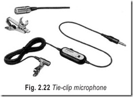
There is another type of microphone with a similar purpose, but even more convenient, now gaining popularity. This is the tie-clip or lapel unit shown in Fig 2.22. This is a tiny microphone supported by a small mount which can be clipped on to a tie, lapel, or other convenient part of clothing. One of the prime requirements for such an instrument is small size and lightness. This rather cuts out the moving-coil transducer as there is a practical limit to the minimum size of cone/ coil assemblies, also the need for a powerful magnet makes it too heavy for this application.
Here again electret system comes to its own. These units can be made very small and are inherently light. Although they need an internal amplifier, these can be formed on a tiny chip of silicon in the form of an integrated circuit, and so add hardly anything to the bulk or weight.
A low voltage is needed to power the amplifier, but the current drain is very small, between 160-400 µA, so a small single cell can be used and still have an appreciable working life. Some microphones use a pen cell which is fitted in the microphone jack-plug, the current passing along the microphone cable, while others use a single mercury cell contained in the microphone itself. These are small disc-shaped cells, looking something like a button, and being only a few millimeters thick take up very little room. Battery life ranges from 5,000 to 10,000 hours or even more. In the case of capacitor transducers higher voltage and current is required, so this cannot be supplied from an internal battery but must be fed along the cable in some way.
As with the lavalier method of mounting, the frequency characteristic of the electret makes it very suitable for the purpose. Chest cavity resonance is less of a problem with the tie-clip or lapel unit because the microphone is not supported directly on the chest but stands off to some extent.
WIRELESS MICROPHONES
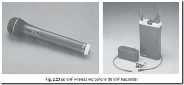
The ultimate in mobility is afforded by the wireless (radio microphone) because with this there is no connecting cable and the user is free to move around over a distance of several hundred metres. There are two basic types, one where the radio transmitter is contained within the casing of the actual microphone, and the other which takes the form of a slim pocket unit about the size of a wallet into which an ordinary microphone can be plugged.
The integral microphone/transmitter unit, Fig. 2.23, is rather larger than a normal gun microphone as batteries must be accommodated as well as the transducer and transmitter. In order to obtain sufficient power for the transmitter, the batteries are at least 9V, but the size limits the capacity. The average life is three to five hours, but rechargeable batteries are often fitted to make the instrument more economic to run.
With the separate pocket transmitter a lavalier or tie-clip microphone can be used to give complete freedom to the user. The aerial takes the form of a short flexible lead which trails from the microphone. Usual length is a quarter wavelength at the permitted frequencies of the carrier wave.
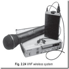
The transmission is picked upon a special receiver which tunes to the frequency used and demodulates the signal delivering an audio frequency output which can then be applied to an amplifier or recorder in the normal way.
There are fifteen frequencies allocated for wireless microphones and all units work on any one of these. Interference is no problem because of the short range, it being unlikely that another user will be operating on the same frequency within about half a kilometer.
The frequencies are in four groups: firstly a group with a wide bandwidth, 174.1, 174.5, 174.8, and 175.1 MHz. The second group is of narrow bandwidth, the frequencies being 174.6, 174.675, 174.77, 174.885, and 175.020 MHz. The third group is also of narrow bandwidth, being reserved for teaching deaf children in schools; these are 173.4, 173.465, 173.545 and 173.64 MHz. In addition, in certain circumstances, the frequencies of 174.65 and 174.95 MHz are allocated for communication on work sites. An ordinary FM receiver will not pick up wireless microphone transmissions.
The narrow bandwidth specification is for a deviation of + 20 kHz, and is suitable for most speech applications. The wide bandwidth allocations allow a deviation of + 75 kHz and give the better quality reproduction required by stage and cabaret artists.
The transmitter output power must not exceed 50 mW in the case of narrow band transmitters, and 10 mW with the wide band units.
Certain specifications also apply to the receiver. Signal to noise ratio must be better than 30 dB and selectivity such that a signal with a deviation of + 10 kHz, 70 kHz away from the wanted signal in the case of narrow band receiver, and with a deviation of + 2.5 kHz, at 200 kHz away from the wanted signal in the case of wide band receiver will not produce an increase of noise plus unwanted signal of more than 3 dB in the output.
An interfering signal of 3 mV should not give a signal in the output greater than 10 dB above noise level in the case of wideband receiver and 20 dB above with that of the narrow band unit.
It is possible for any receiver to generate and radiate a signal from the local oscillator which is part of the superheterodyne circuit universally used. The specification stipulates that any such signal radiated from the receiver’s aerial should not exceed 2.5 µW at any frequency.
These stringent requirements serve to protect the users from the effects of jamming and interference which undoubtedly would be common if such controls were absent. VHF wireless system is shown in Fig. 2.24.
DUAL-UNIT MICROPHONES
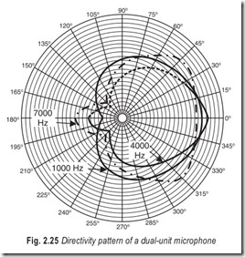
Microphones are available which make use of two units to secure a particular directional pattern. A dynamic unit is often combined with a ribbon unit. Fig. 2.25 shows the directional pattern which results when a bidirectional velocity unit and a nondirectional dynamic unit are combined.
The resultant directivity pattern is a cardioid. Other units are also combined to secure specific directivity patterns.
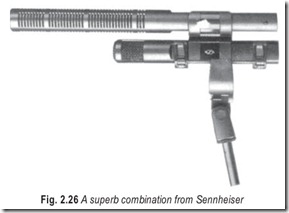
A superb combination from Sennheiser is shown in Fig. 2.26. The MKH 30 is a pressure gradient microphone with a figure-of-eight directivity, optimising wide frequency response, lateral sound rejection and extremely low-inherent noise.
The MKH 30 is matched with the remarkable directivity of the MKH 60, a supercardioid microphone, to enhance the stereo-image. Low frequency ambience and vibration pickup is minimised by efficient roll- off filters.
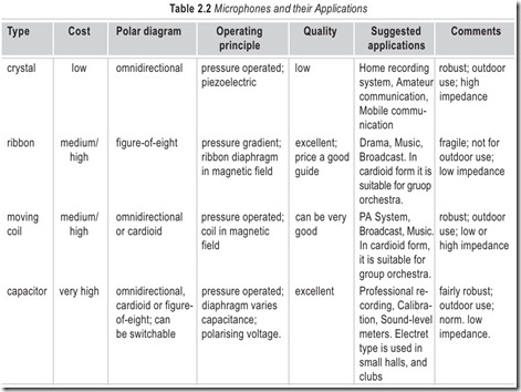
Each microphone can be used separately when stereo operation is not required. Suggested applications of different types of microphones are given in Table 2.2.
ELECTRICAL, MECHANICAL AND ACOUSTICAL ANALOGS
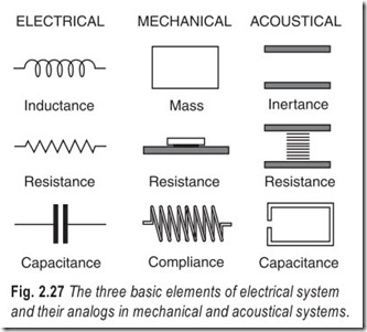
Any acoustical system can be represented in terms of an equivalent electrical or mechanical system. This is shown in Fig. 2.27.
The physicist freely uses these equivalents in setting up his mathematical approach in analysing a given system. For example, the effect of a cabinet on the functioning of a loudspeaker is clarified by thinking of the air in the enclosed space as acting like a capacitor in an electrical circuit, absorbing and giving up the energy imparted by the cone movements.
Figure 2.27 shows three basic elements in electrical, mechanical and acoustical systems. Inductance in an electrical circuit is equivalent to mass in a mechanical system and inertance in an acoustical system. Capacitance in an electrical system is analogous to compliance in a mechanical system and capacitance in an acoustical system. Resistance is resistance in all three systems, whether it be frictional loss offered to air particle movement in glass fibre, frictional losses in a wheel bearing, or resistance to flow of current in an electrical circuit.
EXERCISES
Descriptive Questions�
1. What are the characteristics of microphones? Explain.
2. Explain the significance of a polar diagram.
3. With the help of a diagram explain the working of a dynamic microphone.
4. How does a ribbon microphone differ from a dynamic microphone?
5. How does an electret microphone differ from a capacitor microphone?
6. What are the limitations of crystal microphones?
7. Explain the significance of a hum-bucking coil.
8. In which microphones is a built-in transformer a necessity and why?
Multiple Choice Questions
1. Microphones are electroacoustic transducers which convert
(a) acoustic energy to electrical energy
(b) electrical energy to acoustic energy
(c) acoustic energy to mechanical energy
(d) mechanical energy to acoustic energy
2. The unit of sound pressure used for rating microphones is
(a) pascal (b) bar
(c) watt (d) decibel
3. The polar diagram of a true omnidirectional microphone is
(a) perfect circle (b) figure-of-eight
(c) cardioid (d) none of the above
4. Moving coil microphones are
(a) active transducers (b) unidirectional
(c) both (a) and (b) (d) neither (a) nor (b)
5. Moving coil microphones are
(a) omnidirectional (b) unidirectional
(c) neither (a) nor (b)
6. Carbon microphones
(a) produce an emf (b) modulate the current from an external battery
(c) both (a) and (b) (d) neither (a) nor (b)
7. The natural impedance of a ribbon microphone is
(a) very low (b) low
(c) high (d) very high
8. The ordinary dynamic microphone is
(a) omnidirectional (b) unidirectional
(c) nondirectional (d) either (a) or (b)
9. The polar diagram of a capacitor microphone can be modified by
(a) varying the polarising voltage (b) varying the pressure gradient
(c) both (a) and (b) (d) neither (a) nor (b)
10. The half-life of electret microphones varies from
(a) 100 to 250 years (b) 250 to 500 years
(c) 100 to 1000 years (d) 250 to 1000 years
11. The construction of gun microphones makes use of the principle of
(a) diffraction (b) interference
(c) reflection (d) refraction
12. A device which magnifies sound levels acoustically is the
(a) lavalier microphone (b) gun microphone
(c) parabolic reflector (d) ribbon microphone
Fill in the Blanks
1. For most high quality microphones impedance is ……………………………………
2. Cassette recorders of good quality are not, as a rule, designed to take…………………………………… impedance microphones.
3. Microphones do not respond equally to coming from all …………………………………….
4. An …………………………………… microphone is most commonly used for general recording.
5. An inset pattern of carbon microphone is in general use for …………………………………….
6. The carbon microphone generates a continuous …………………………………….
7. The double crystal unit is called a …………………………………….
8. The equivalent circuit of a crystal microphone consists of a…………………………………….in series with a……………………………………..
9. One of the refinements in better quality dynamic microphones is ……………………………………..
10. The output voltage of a ribbon microphone is…………………………………….and so also is its……………………………………..
11. In order to produce large capacitance variations the …………………………………….must be high.
12. A self-contained amplifier is necessary with ……………………………………. microphones.
ANSWERS
Multiple Choice Questions
|
1. (a) |
2. (b) |
3. (a) |
4. (a) |
5. (a) |
6. (b) |
|
7. (a) |
8. (c) |
9. (a) |
10. (c) |
11. (b) |
12. (c) |
Fill in the Blanks
|
1. low |
2. |
high |
3. sounds, directions |
|
4. omnidirectional |
5. |
telephone systems |
6. hiss |
|
7. bimorph |
8. |
voltage source, capacitor |
9. a hum bucking coil |
|
10. very low, impedance |
11. |
polarising voltage |
12. ribbon |
