As Equation (11.96) shows, to compute the time harmonics conductor losses, the variation of stator and rotor leakage inductances and resistances with frequency due to skin effect is needed. This problem has been treated in detail, for a single, unassigned, frequency in Chapter 9, both for the stator and rotor. Here we simplify the correction factors in Chapter 9 to make them easier to use and interpret.
In essence, with different skin effect in the slot and end-connection (end ring) zones, the stator and resistance Rs(fν) is
Rs( )fν = Rsdc KRss ( )fν llstackcoil + KRse( )fν lendconlcoil (11.107)
lcoil–coil length, lendcon–coil end connection length.
KRss > 1 is the resistance skin effect correction coefficient for the slot zone and KRse corresponds to the end connection. A similar expression is valid for the stator phase leakage inductance.
Lsl( )fν = Lsldc KXlss( )fν llstackcoil + KXlse( )fν lendconlcoil (11.108)
KXlss and KXlse are leakage inductance correction factors.
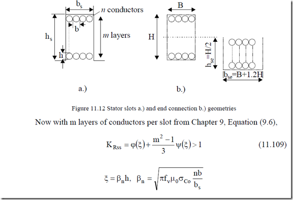
h – conductor height, n – conductors per layer, b – conductor width (or diameter), bs – slot width. Equation (11.109) is strictly valid for rectangular slots (Figure 11.12). More evolved methods, as described in Chapter 9, may be used for general shape slots.
The same formula (11.109) may be used for end connections coefficient
KRse but with bse instead of bs, hse instead of hs,and m/2 instead of m.
In a similar way, the reactance correction coefficient KXss is (Equation (9.7))
KXss = ϕ ξ +‘( ) (mm22− ψ ξ1) ‘( ) <1 (11.110)
Also, from (9.4) and (9.8), (9.9)
ϕ ξ = ξ( ) ![]() ; ψ ξ =( ) 2ξ
; ψ ξ =( ) 2ξ![]() (11.111) ϕ ξ ='( )
(11.111) ϕ ξ ='( ) ![]() ; ‘ψ ξ =( )
; ‘ψ ξ =( ) ![]() (11.112)
(11.112)
As the number of layers in the virtual slot of end connection is m/2 and the slot width is much larger than for the actual slot bse – bs ≈ 1.2hs ≈ (4 – 6)bs, the skin effect coefficients for the end connection zone are smaller than for the slot zone but still, at high frequencies, they are to be considered.
For the cage rotor resistance Rr and leakage inductance Lrl, expressions similar to (11.107 – 11.108) are valid.
Rr ( )fν = RbdcKRb( )fν + RerdcKRe( )fν (11.113)
Lrl( )fν = LbdcKXb( )fν + LerdcKXe( )fν (11.114)
Again, expressions (11.109) and (11.110) are valid, but with m = 1, with nb = bs, and σAl in (11.109).
Also, in (11.110), ξ is to be calculated with hse = h, bse = bs + Khh. In other words, the end ring has been assimilated to an end connection, but the factor Kh should be 1.2 for a distant ring and less than that for an end ring placed close to the rotor stack.
Example 11.6. Time harmonics conductor losses. An 11 kW, 6 pole, f1 = 50 Hz, 220 V induction motor is fed from a PWM converter at carrier frequency fν = 20 kHz. For this frequency, the voltage Vν = 126 V (see [14]).
For the rotor: ξ = 18.38, KXb = 0.0816, KRb = 18.38, Rr’(fν) = 2.2 Ω (end ring resistance neglected), X’rl = 2πfν⋅Lrl(fν) = 47.9 Ω, and for the stator: ξ =
3.38, KRss = KRse = 79.4, Rs(fν) = 11.9 Ω, KXss = KXse = 0.3, Xsl = 2πfν⋅Lrl(fν) =
63.3 Ω
The harmonic current Ιν is
Now the conductor losses at 20 kHz are
(Pcon )20kHz = 3(R’r +Rs )Iν2 = 3 2.2( +11.9 1.) 122 = 53.06W
We considered above Vν ≈ V1,which is not the case, in general, although in some PWM strategies at some modulation factor values, such a situation may occur.
11.12. TIME HARMONICS INTERBAR ROTOR CURRENT LOSSES
Earlier in this chapter we dealt with space harmonic induced losses in skewed noninsulated bar rotor cages. This phenomenon occurs also due to time harmonics. At the standard fundamental frequency (50 or 60 Hz) the additional transverse rotor losses due to interbar currents are negligible. In high frequency motors (f1 > 300 Hz), these losses count. [11] Also, time harmonics are likely to produce transverse losses for skewed noninsulated bar rotor cages.
To calculate such losses, we may use the theory developed in Paragraph 11.6, with S = 1, ν = 1 but for given frequency fν and voltage Vν.
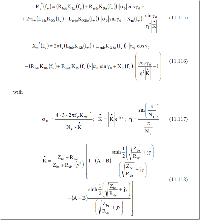
However, to facilitate the computation process, we adopt the final results of Reference [11] which calculates the rotor resistance and leakage reactance including the skin effect and the transverse (interbar currents) losses, R r*( ) (fν = R bdcKRb ( )fν + RerdcKRe ( ))fν ⋅ α0 cosγ +0
|
cosγ |
(11.116) |
![]() + π2 fν(LbdcKXb ( )fν + LerdcKXRe ( )fν )⋅ α0 sin γ +0 Xm ( )fν ⋅ sin γ•0 (11.115)
+ π2 fν(LbdcKXb ( )fν + LerdcKXRe ( )fν )⋅ α0 sin γ +0 Xm ( )fν ⋅ sin γ•0 (11.115)
![]()
![]() − (R bdcKRb ( )fν + RerdcKRe ( )fν )⋅ α0 sin γ +0 Xm ( )fν ⋅ η2 K• 0 −1
− (R bdcKRb ( )fν + RerdcKRe ( )fν )⋅ α0 sin γ +0 Xm ( )fν ⋅ η2 K• 0 −1
where γ is the skewing angle.
A and B are defined in (11.75) and (11.76). Zbe and Rde are defined in (11.73) and refer to rotor bar impedance and equivalent rotor end ring and bar tooth wall resistance Rde is reduced to the rotor bar.
Xm(fν) is the airgap reactance for frequency fν and fundamental pole pitch, Xm ( )fν = Xm( )f1 ⋅ ffν1 (11.119)
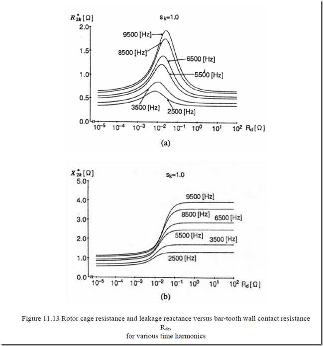
In [11], for a 500 Hz fundamental, high speed, 2.2 kW motor, the variation of rectangular bar rotor resistance Rr*(Rde) for various frequencies was found to have a maximum whose position depends only slightly on frequency (Figure 11.13a).
The rotor leakage reactance Xrl*(Rde) levels out for all frequencies at high bar-tooth wall contact resistance values (Figure 11.13b).
We should note that Equations (11.115) and (11.116) and Figure 11.13 refer both to skin effect and transverse losses.
As the skin effect at, say, 9500 Hz is very strong and only the upper part of the rotor bar is active, the value of transverse resistance Rde is to be increased in the ratio
Rde = Rdedc δAlh( )fν (11.120)
This is as if we would read values of Rr*, Xrl* in Figure 11.13 calculated for (Rde)dc at the abscissa Rde of (11.120).
Also, as Xrl* increases with Rde, the harmonic current and conductor losses tend to decrease for large Rde.
Increasing the frequency tends to push the transverse resistance Rde to larger values, beyond the critical value and thus lower interbar currents and losses are to be obtained.
However, such a condition has to be verified up to carrier frequency so that a moderate influence of interbar currents is secured.
11.13. COMPUTATION OF TIME HARMONICS CORE LOSSES
The computation of core losses for high frequency in IMs is a very difficult task. However, for the case when δFe < d (large skin effect) and all the flux paths are located around stator and rotor slots and on rotor surface in a thin layer (due to airgap flux pulsation caused by stator slot openings), such an attempt may be made easily through analytical methods.
Core losses may also occur due to axial fluxes, in the stack-end laminations because of end connection high frequency leakage flux. So we have three types of losses here.
a. Slot wall time harmonic core losses
b. Airgap flux pulsation (zig-zag) time harmonic core losses
c. End connection leakage flux time harmonic core losses
11.13.1. Slot wall core losses
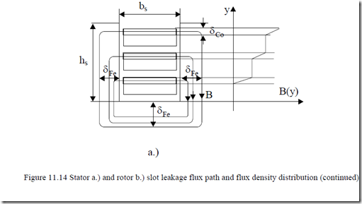
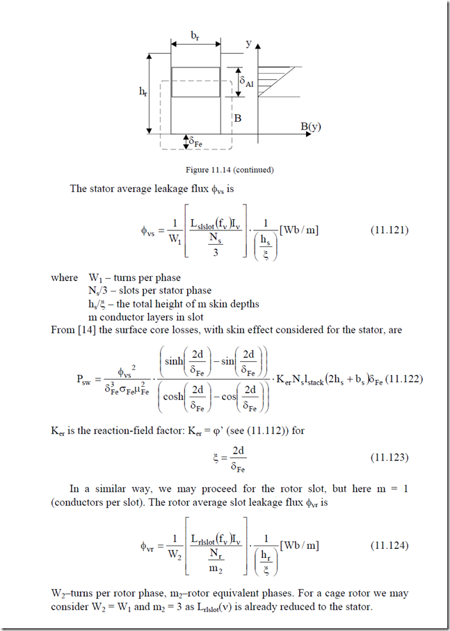
Due to the strong skin effect, the stator and rotor currents are crowded toward the slot opening in each conductor layer (Figure 11.14).
In a similar way, we may proceed for the rotor slot, but here m = 1 (conductors per slot). The rotor average slot leakage flux φνr is
φνr = W12 LrlslotmN( )2rfν νI ⋅ h1ξr [Wb/ m] (11.124)
W2–turns per rotor phase, m2–rotor equivalent phases. For a cage rotor we may consider W2 = W1 and m2 = 3 as Lrlslot(ν) is already reduced to the stator.
The rotor slot wall losses Prw are
2d
![]() Prw = δ σ µ3FeφνFer2 Fe2 ⋅ coshsinh δδ2FeFed −−sincosδ2δ2FedFed ⋅K N ler r stack (2hr + br )δFe (11.125)
Prw = δ σ µ3FeφνFer2 Fe2 ⋅ coshsinh δδ2FeFed −−sincosδ2δ2FedFed ⋅K N ler r stack (2hr + br )δFe (11.125)
11.13.2. Zig-zag rotor surface losses
The time harmonic airgap flux density pulsation on the rotor tooth heads, similar to zig-zag flux, produces rotor surface losses.
The maximum airgap flux density pulsation BνK, due to stator slot opening is π β
BνK = 4 2 −β Bνg (11.126)
The factor β (bos/g) has been defined in Chapter 5 (Figure 5.4) or Table 10.1. It varies from zero to 0.41 for bos/g from zero to 12. The frequency of BνK is fν(Ns/p1 ± 1). Bνg is the fν frequency airgap space fundamental flux density. To calculate Bνg, we have to consider that all the airgap flux is converted into leakage rotor flux. So they are equal to each other.
π2 Bνgτlstack W K1 w1 = I Lν rν (11.127)
Based on (11.126 and 11.127) in Reference [14], the following result has been obtained for zig-zag rotor surface losses:
2d
2
![]() Pzr = 2(π δD Fe )81 16π 2β−β 2 Bνg2lstack2 ⋅ δ σ µK C3Feer Feν1r2Fe ⋅ coshsinh δδ2FeFed −−sincosδ2δ2FedFed
Pzr = 2(π δD Fe )81 16π 2β−β 2 Bνg2lstack2 ⋅ δ σ µK C3Feer Feν1r2Fe ⋅ coshsinh δδ2FeFed −−sincosδ2δ2FedFed
(11.128)
sin KπK2 2 sin KπK2 2
![]() Cν1r = K Kπ2R’2 + K Kπ R’2 −
Cν1r = K Kπ2R’2 + K Kπ R’2 −
2R’ R’ (11.129)
![]() − sin KK Kπ2KπR’2 2 ⋅ sin K K KππR’K2 2 ⋅ cos K K2πR’2 << 1
− sin KK Kπ2KπR’2 2 ⋅ sin K K KππR’K2 2 ⋅ cos K K2πR’2 << 1
2R’ R’
K = Np1s ±1; K2 = (tr −trbor ); R’= 2Npr1 (11.130)
where tr–rotor slot pitch; bor–rotor slot opening.
Zig-zag rotor surface losses tend to be negligible, at least in small power motors. End connection leakage core losses proved negligible in small motors. In high power motors, only 3D FEM are able to produce trustworthy results. In fact, it seems practical to calculate only the slot wall time harmonics core losses in the stator and rotor. For the motor, in Example 11.6 in [14], it was found that
Psw + Prw’ = 6.8 + 7.43 = 14.23W. This is about 4 times less than conductor losses at 20 kHz.
11.14. LOSS COMPUTATION BY FEM
The FEM, even in its 2D version, allows for the computation of magnetic field distribution once the stator and rotor currents are known. Under no-load, only the stator current waveform fundamental is required. It is thus possible to calculate the additional currents induced in the rotor cage by conjugating field distribution with circuit equations.
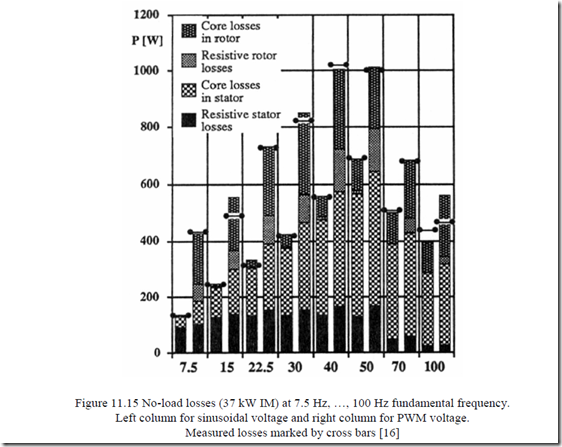
The core loss may be calculated only from the distribution of field in the machine with zero electrical conductivity in the iron core. This is a strong approximation, especially at high time harmonic frequencies (see previous paragraphs). In References [15, 16] such a computation approach is followed for both sinusoidal and PWM voltages. Sample results of losses for a 37 kW motor on no-load are shown on Figure 11.15. [16]
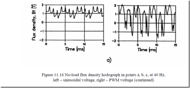
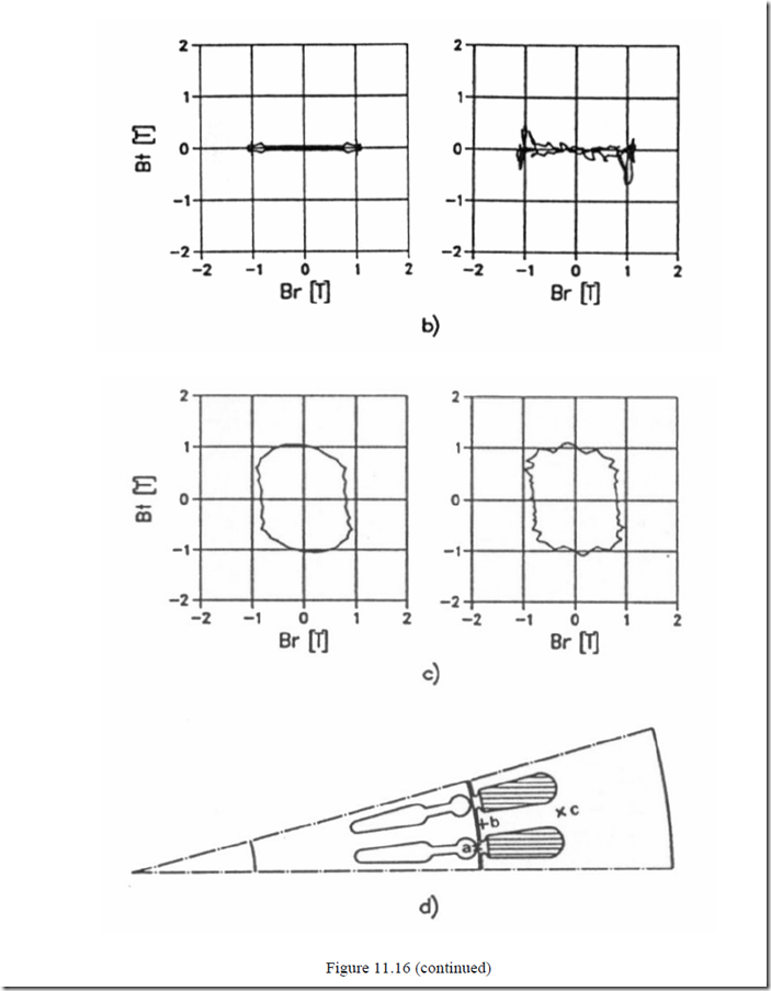
More important, the flux density radial (Br) and tangential (Bt) flux density hodographs in 3 points a, b, c (Figure 11.16c) are shown on Figure 11.16a, b. [16] This is proof that the rotor slot opening (point a) and tooth (point b) experience a.c. field while point c (slot bottom) experiences a quasi-traveling field. Although such knowledge is standard, a quantitative proof is presented here.
When the motor is under load, for sinusoidal voltage supply, FEM has been also used to calculate the losses for a skewed bar cage rotor machine. Insulated bars have been used for the computation. This time, again, but justified, the iron
skin effect was neglected as time harmonics do not exist. Semiempirical loss formulas, as used with analytical models, are still used with FEM.
The influence of skewing in the rotor is considered separately, and then by using the coupling field-circuit FEM. The stack was sliced into 5 to 8 axial segments properly shifted to consider the skewing effects. [17]
The already documented axial variation of airgap and core flux density due to skewing changes the balance of losses by increasing the stator fundamental and especially the rotor (stray) core losses and decreasing the rotor stray (additional) cage losses.
In low power induction motors, where conductor losses dominate, skewing tends to reduce total losses on load, while for large machines where core loss is relatively more important, the total losses on load tend to increase slightly due to skewing. [17]
The network – field coupled time – stepping finite element 2D model with axial stack segmentation of skewed-rotor cage IMs has been used to include also the interbar currents [18].
The fact that such complex problems can be solved by quasi 2D–FEM today is encouraging as rather reasonable computation times are required, However, all the effects are mixed and no easy way to derive design hints seems in sight.
For other apparently simpler problems, however, as the usage of magnetic wedges for stator slots in large machines, FEM is extremely useful. [19] A notable reduction of rotor stray core losses is obtained. Consequently, higher efficiency for open stator slots is expected.
A similar situation occurs when the hysteresis losses in a cage IM are calculated by investigating the IM from rated to zero positive and negative slip. [20]
A pertinent review of FEM usage in the computation of IM performance (and losses) is given in Reference [21].
