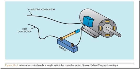
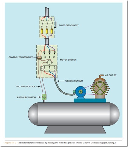
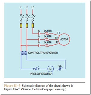
Control circuits can be divided into two major types: two-wire control circuits and three-wire control circuits. A two-wire control circuit can be a simple switch that makes or breaks connection to a motor (Figure 18 – 1). A good example of this type of control is the single-phase manual starter shown in Figure 3 – 1. Two-wire control circuits also control the operation of three-phase motors by controlling the power applied to the motor starter coil. A good example of this type of control is an air compressor (Figure 18 – 2). The
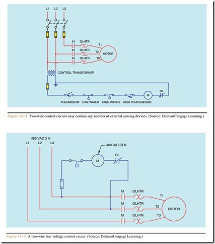
pressure switch is used to control the motor starter. A schematic diagram of the circuit in Figure 18 – 2 is shown in Figure 18–3. Two-wire control circuits are so named because only two wires are required to control the operation of the circuit. Two-wire circuits may incorporate several different external sensing devices, as shown in Figure 18 – 4. This circuit is a basic control for a hot water boiler. The thermostat controls the action of the burner. Two float switches are used to sense low and high water conditions in the boiler. A high limit temperature switch will stop the burner if the water temperature should become excessive.
It is not unusual for two-wire control circuits to use line voltage controls. Line voltage controls are simply controls that do not employ the use of a control trans- former to change the voltage to a lower value. The coils of motor starters and contactors are available that operate at different voltages. Common voltage values for motor starter coils (in volts AC) are: 24, 120, 208, 240, 277, 480, and 560. A two-wire line voltage control circuit is shown in Figure 18–5.
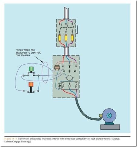
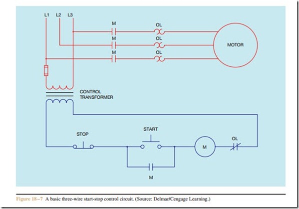
Three-wire control circuits are characterized by the use of momentary contact devices such as push buttons. When push buttons control the operation of a motor, three wires are run from the push-button control station to the starter (Figure 18 – 6). A simple three-wire push- button control circuit is shown in Figure 18 – 7. Three- wire control is used to a much greater extent through- out industry than two-wire control because of its flexibility. Pilot control devices such as push buttons, float switches, and limit switches can be mounted in re- mote locations, whereas while the motor starter can be located close to the motor it controls or in a control cab- inet with other control components. Another advantage of three-wire control circuits is that in the event of a power failure they will not restart automatically when power is restored. This can be a major safety issue in many instances. Three-wire controls depend on a set of normally open contacts, generally called holding, maintaining, or sealing contacts, connected in parallel with the start push button to maintain the circuit once the normally open start button is released. These con- tacts are labeled M in Figure 18 – 7.
Review Questions
1. What are the two major types of control circuits?
2. How is it possible for a two-wire control circuit to control the operation of a three-phase motor?
3. Refer to the schematic shown in Figure 18–4.
What type of switch is the thermostat?
a. normally open temperature switch.
b. normally closed temperature switch.
c. normally open held closed temperature switch.
d. normally closed held open temperature switch.
4. Refer to the schematic shown in Figure 18–4.
What type of switch is the low water switch?
a. normally open float switch.
b. normally closed float switch.
c. normally open held closed float switch.
d. normally closed held open float switch.
5. What generally characterizes a three-wire control circuit?
6. Explain the function of a holding contact.
7. How are holding contacts connected?
