Motional Impedance
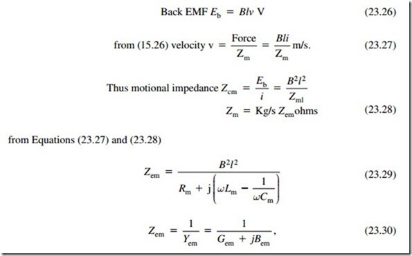
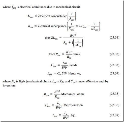
The moving coil system is a reversible transducer, a current through the coil will produce a force, and the resultant velocity of the coil will produce an EMF. This voltage will be a function of velocity, conductor length, and magnetic field strength; thus if an external EMF is applied to the coil the resultant motion will generate a back EMF (180° out of phase), which will tend to counteract the forward current flow, thus increasing the electrical impedance. This is “motional impedance.”
If the motion of the system can be prevented by applying an infinite mechanical impedance (Zmx in Figure 23.16), there will be no back EMF and the electrical impedance will be only the voice coil resistance and inductance (blocked impedance). Reducing the mechanical impedance (reducing mass and resistance and increasing compliance) will result in an increase in velocity and the motional impedance will be increased. Intuitively, this indicates that motional impedance will be proportional to Bl and an inverse function of the mechanical impedance. The common factor is the velocity of motion.
It will be noted that in the analogue inductance (mass) in the mechanical circuit will become a capacitance in the electrical circuit, etc.
At mechanical resonance
and the mechanical impedance Zm will have a minimum value = Rm. The velocity will be maximum, thus the back EMF and motional impedance will be maximum, indicating a parallel resonance. It will be seen that series components in the mechanical circuit appear as parallel components in the electrical side and vice versa.
Analogue Models
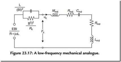
We can now assemble the various parameters to produce a basic analogue for a loudspeaker. Figure 23.17 shows the low-frequency analogue referred to the mechanical side. The quantity fc represents the total force acting in the equivalent circuit to produce the voice coil velocity uc:
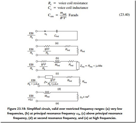
Let us divide the frequency region into five parts and treat each part separately by simplifying the circuit in Figure 23.18 to correspond to that part alone. In region A, where the loudspeaker is stiffness controlled, the power output increases as the fourth power of frequency, or 12 dB/octave. In region B, at resonance frequency 0)o the power output is determined by the total resistance because Xm passes through zero. For large values of Bl and small values of Rc, the total circuit resistance becomes sufficiently large so that the resonance is more than critically damped. The sound pressure will increase linearly with frequency (+6 dB/octave). In region C, the power output (and sound pressure) approaches a constant value, provided that the circuit impedance approximates a pure mass reactance. That is to say, RMR and Xm2 both increase as the square of the frequency.
Figure 23.17 shows that the inductance of the voice coil is reflected into the mechanical circuit as a compliance [very much smaller than Cms, which will resonate with the total mass at a midfrequency (usually 150–700 Hz); see Figure 23.18]. At this frequency, the total electrical impedance is resistive, has the lowest absolute value, is the value that is (or should be) quoted as the rated impedance in the manufacturer’s specification, and corresponds to (d) in Figure 23.18.
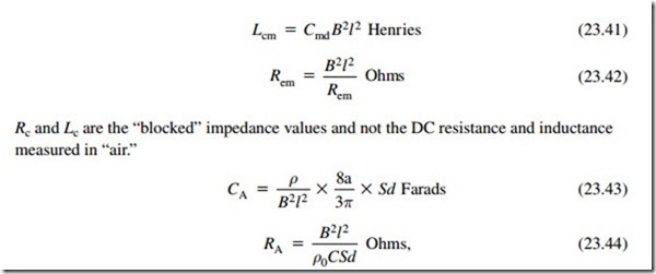
Instead of referring all the parameters to mechanical mesh, it is sometimes more convenient to refer to the electrical input (see Figure 23.19) in which
where a is diaphragm radius and Sd is diaphragm area.
It should be noted that the factor 8a/π in Equation (23.43) is actually the “end correction” used to describe the accession to inertia acting on one side only of a rigid piston of radius ‘a’ vibrating in an infinite baffle. The air loading on the back side of the diaphragm is determined by the loading presented by the enclosure.
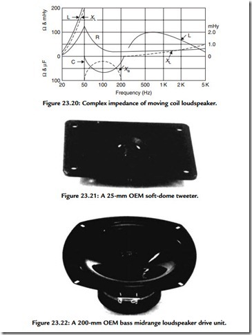
Figure 23.20 shows the impedance of a 300-mm (12-inch) loudspeaker in an 85-liter enclosure (3 ft3). It will be seen that the modulus of impedance rises to 125 ohms at the mechanical resonant frequency of 55 Hz, drops to 8 ohms at the series resonance, and rises to 40 ohms at 10 kHz. Of equal interest is the reactive component: below the first resonance an inductive reactance is presented to generator (rising to infinity at resonance), while between the two resonances a capacitive reactance is presented. At 100 Hz the effective capacitance is about 90 μF, and at that frequency the phase angle
is 45°. Above the second resonance the impedance rises slowly. It will be seen that the design of a successful moving coil loudspeaker owes as much to art as science (Figures 23.21 and 23.22). CAD can and does simplify much of the detail work, but after the basic design parameters (diaphragm size, magnetic field strength, conductor length, etc.) have been calculated, the nub of the problem is what diaphragm material, adhesives, cradle material and shape, and so on to use—the art of loudspeaker design is 5% inspiration, 95% perspiration, plus the essential compromise.
