DISTORTION IN DISC EQUIPMENT
Some distortion is always present in the sound reproduced from a gramophone record or magnetic tape. The loudspeaker, pick-up and recording head also make substantial contributions to the distortion. High-quality reproduction will only be achieved if careful attention is also paid to the sound input source to the amplifier.
It is not possible to eliminate distortion entirely. There would still be some distortion which is bound to occur when discs or tapes are used.
LOUDSPEAKERS
The choice of a suitable loudspeaker is very important for both disc and tape reproduction. While it would be wrong to assume that price is the only guide available, normally the higher grades of loudspeaker will justify their cost by giving correspondingly better reproduction. The choice should never be made hastily. It is not sufficient to listen to one or two records because it is easy to construct a system which will sound impressive at first hearing. Extended periods of listening to music are desirable to discover if mental fatigue is likely to be caused by the system. Furthermore, because it is easier to judge speaker quality by listening to comparatively simple sounds rather than to full orchestral recordings, the system should also be tested by assessing the fidelity with which good-quality broadcast speech is reproduced.
A simple direct-radiator loudspeaker—that is, single cone unit handling the entire range of frequencies— can give excellent results when mounted in a suitable enclosure. It is important to remember thatthis enclosure should always be that specified by the speaker manufacturer since it is not possible to design a suitable cabinet without knowing accurately the basic performance of the loudspeaker unit. One of the main disadvantages of all types of simple direct radiators is that the high-frequency response is very directional. This fact, however, can to some extent be overcome by using the loudspeaker in conjunction with some form of reflector. The reflector can be built into the cabinet, or a corner of the room can be used for the purpose. The effect of the reflector is to distribute the high-frequency components in a more random manner so that with the adequate treble boost provided by the amplifier, good results will be obtained.
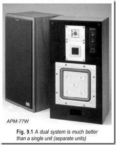
There is no doubt, however, that even the simplest of dual systems is much better than a single unit. Such a dual system may consist of two direct radiators—for example, a 12 in unit for the bass-end of the spectrum and a 5 in unit for the middle and treble components—used in conjunction with a suitable cross-over network. While the effective frequency response may not be very much increased by this type of dual system, various forms of distortion will be reduced considerably, added to which there will be a better distribution of high frequencies from the smaller source.
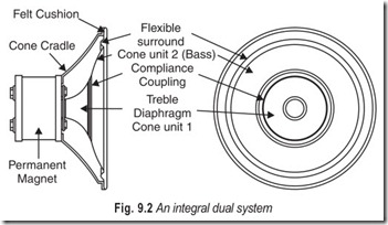
Dual systems using twin direct radiators are available in two forms; either with two completely separate units, Fig. 9.1 each mounted in its own enclosure or, alternatively, with the high frequency unit mounted on some form of modified frame, making it an integral part of the low frequency unit, as shown in Fig. 9.2 .
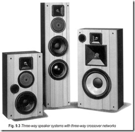
Greater improvement may be obtained by using three loudspeaker units together with a three-way crossover network, Fig. 9.3. This extends the frequency range and reduces distortion still further, as well as providing a greater range of distribution patterns.
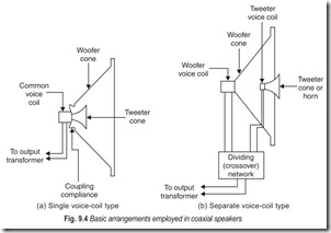
The most complicated form of dual loudspeaker system is that which is horn loaded over its entire range. This may be achieved by using separate horn assemblies, each associated with a loudspeaker unit covering part of the frequency spectrum. Alternatively loudspeakers of the concentric type can be used.
Such systems are always expensive but they have certain advantages; the electroacoustic conversion efficiency is high, the acoustic damping for the entire audio-range is much improved over that of any simple direct- radiator system and the larger size of the bass horn gives better realism. This is shown in Fig. 9.4.
DISC EQUIPMENT-RECORDING CHARACTERISTICS
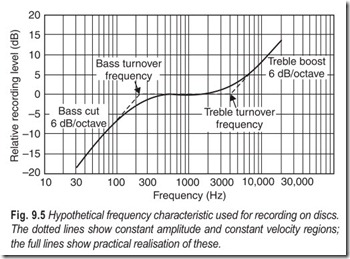
Magnetic recording heads are normally used for cutting discs ; the stylus is attached either to the moving iron armature or to the moving coil. The velocity at which the stylus vibrates (measured as the stylus passes its equilibrium position) is directly proportional to the recording-signal strength, so that, for a constant voltage, the velocity is constant, and the amplitude or width of the groove is inversely proportional to the signal frequency. This is known as constant velocity recording.
If the amplitude at high frequencies is chosen to give an acceptable signal-to-noise ratio, then the amplitude at low frequencies will be excessive. Distortion will be high and too much space will be needed between adjacent rings of the groove to ensure that breakthrough from one ring to another does not occur. Thus, some restriction of the amplitude is desireable at these low frequencies and, to achieve this, bass signal voltages from the recording amplifier are attenuated before being recorded. Recordings in which the maximum width of the groove is restricted to some limit are known as constant amplitude recordings.
Because of the difficulty in maintaining a satisfactory signal-to-noise ratio if a constant velocity characteristic is used at high frequencies, it is normal to boost treble signals from the recording amplifier before recording them. Consequently, a recording characteristic indicating the variation of recording voltage with frequency can be divided into three sections: the bass section showing voltage attenuation; the middle section showing—constant velocity recording ; and the treble section showing voltage boost.
An imaginary recording characteristic is drawn in Fig. 9.5. The frequencies at which the characteristic changes from one section to another are called the turnover frequencies. The slope of the bass and treble sections of the characteristic depends on the degree of attenuation or boost applied to the recording signal.
If recordings with a constant amplitude of modulation are required, the stylus velocity must be proportional to the frequency and hence the signal voltage must be halved or doubled as the frequency is halved or doubled and this gives a characteristic slope of 6dB per octave. Actual recording characteristics differ considerably from the imaginary ones of Fig. 9.5. The straight lines of the characteristics cannot be achieved in practice, and actual characteristics are more like the continuous curve shown in Fig. 9.5.
The bass and treble turnover frequencies in actual curves are defined as those frequencies at which the ratios of the recorded voltages to the true signal voltage are 1 : ![]() and
and ![]() : 1 (that is, –3 dB and +3 dB)
: 1 (that is, –3 dB and +3 dB)
respectively. The true signal voltage is assumed, for reference purposes, to be the level of voltage recorded at 1 kHz.
In most practical characteristics, the middle horizontal section is discarded, and only a point of inflection at 1 kHz is retained. The bass and treble sections of practical curves are not produced indefinitely with a constant slope, but are flattened at the limits of the range of audible frequencies.
DISC EQUIPMENT-PLAYBACK CHARACTERISTICS
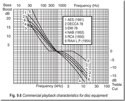
If a magnetic pick-up head is used to reproduce the sound recorded on discs, the output voltage from the head will be proportional to the velocity of vibration of the needle. Consequently, the output from a magnetic head used with recordings made to characteristics of the type shown in Fig. 9.5 will increase with frequency in the bass and treble regions. (This will not be so with crystal pick-up heads as the output of these is proportional to the amplitude of modulation). Thus, correction or equalisation will be required during playback amplification to restore the true level of the signal voltage, and this equalisation should be the converse of the attenuation and boost applied while recording.
The recording characteristics used by the different recording companies before 1955 almost followed the curve shown in Fig. 9.5, but the differences were large enough to make equalisation a matter depending greatly on the records to be played. Many companies issued their own equalisation characteristics, and corrective networks had to be designed with these in mind. Examples of the playback characteristics of the major recording companies are shown in Fig. 9.6.
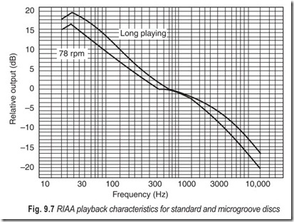
In 1955, however, the majority of these companies agreed to adopt the characteristics of the Recording Industries Association of America (RIAA) which are drawn in Fig. 9.7.
Consequently, there is no need with up-to-date recordings, to adopt the pick-up head and record to each other by using separate equalising networks for each brand of record. Instead, one network (usually in the form of a frequency-selective feedback network) can be incorporated in the amplifier, of course, with the two characteristics for standard and microgroove records, separate networks will still be required for these.
MAGNETIC PICKUP HEADS
Magnetic pickup heads (moving-iron and moving-coil) have basically constant velocity characteristic, the output voltage being proportional to the velocity of vibration of the pickup stylus (measured at its equilibrium position). Output voltages which are quoted for comparing magnetic pickup heads should therefore be given with reference to stylus velocity. This reference can be made directly by quoting the velocity; alternatively the ratio (expressed in decibels) of the actual output voltage to that which would be obtained at some standard velocity (1 cm/s) should be given. Hence, an output voltage could be given as, say, 100 mV at 3.16 cm/s or 100 mV at +10 dB, and both expressions would be equivalent.
Moving-iron magnetic pick-up heads can be divided into three classes, governed by their outputs (measured at a stylus velocity of 3.16 cm/s):
1. Low-output heads Voltages below 20 mV
2. Medium output heads Voltages between 20 and 100 mV
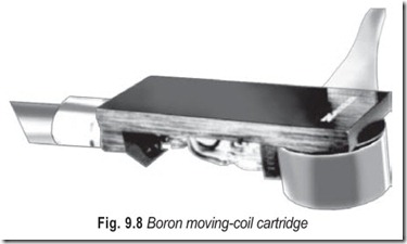
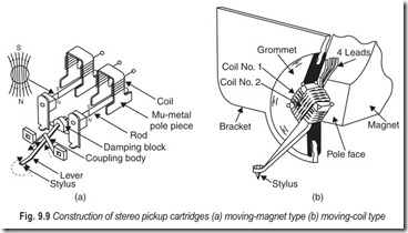
3. High-output heads Voltages above 100 mV.The basic output of a moving-coil pickup head Fig. 9.8, is of the order of millivolts. The lower level of output results from the desirability of lightness of the pickup unit and hence the restriction on the number of turns of the coil.
Both types of head (Fig. 9.9) are suitable for high-quality equipment, although the intrinsically low output of the moving-coil type necessitates the use of a high-ratio pick-up transformer between it and the amplifier. The impedance of magnetic heads is of the order of kilohms at a signal frequency of 1 kHz, and the required loading (that is, the input impedance of the amplifier) for the rated output of the heads is of the order of 100 kW. Their loading should be independent of frequency, otherwise the input signal to the amplifier will also vary with frequency.
CRYSTAL PICKUP HEADS
In a crystal pick-up head a strain is produced in the piezoelectric crystal by the vibration of the stylus as it follows the modulation of the recorded groove. The amplitude of this modulation governs the output voltage of the head.
The rated output voltage of a crystal pickup is always quoted at a particular frequency. This is required for comparison of a recording made to a constant velocity and the amplitude of modulation. Hence, the output voltage—of such a recording is inversely proportional to the frequency.
A typical output voltage from a high-output crystal head would be 1 V at 1 kHz. The output at a frequency of 300 Hz would therefore be about 3 V. It is thus evident that attenuation is desirable at the lower frequencies to provide a balanced output and to prevent the input stage from being over-driven. The highest quality crystal heads have outputs considerably lower than this—a typical value being 0.5 V at 1 kHz.
The impedance of a crystal pick-up head is equivalent to a capacitance, the value of which is of the order of 1000 pF. The optimum load resistance of a crystal head will depend on the method of loading. If it is loaded so that its characteristic is similar to that of a magnetic pick-up head and the load resistance is of the order of 100 kW. If the characteristic is not modified, then an input impedance of the order of megohms is desirable.
STEREO PICKUP HEADS
Pickup heads of stereophonic equipment can be either magnetic or crystal type. The construction of these pickup heads, however, will differ considerably from that of monaural heads. They must be capable of responding to the two-dimensional modulation of the recording groove and of translating the response into two separate signals where as monaural heads have only to follow a lateral displacement and convert it into a single signal. Consequently, there must be two signal generators in each stereophonic head and these must have very similar characteristics. They will, therefore, both be of the same type—both crystal or both magnetic. Also, the pickup stylus will require a vertical compliance comparable with its lateral compliance so that the tip of the stylus can follow the contours of the recording groove faithfully and provide balanced stimuli for the twin generators.
The output voltages obtained from these generators are very much lower than the voltages derived from monaural heads of the same type. Moving-iron stereophonic heads will produce voltages of the order of millivolts for each signal and crystal heads will give signals of the order of 100 mV. The impedance of each section of a stereophonic head will be of the same order as that of the same type of monaural head—about 1 kiloohm for magnetic heads and the equivalent of about 1000 pF for crystal heads.
DISCS
Records are normally made for replaying at three different speeds: 78, 45 or 33 1/3 rpm. The first or standard type of disc is pressed in a hard non-pliable material called shellac. Record wear with this material is relatively high even under good playing conditions. Wear with vinyl, the pliable material used for 45 and 33 1/3 rpm,microgroove type of disc, is very slight under comparable conditions.
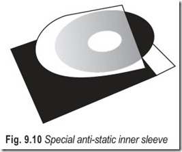
The main trouble with vinyl records is the tendency to collect dust through electrostatic attraction. A special anti-static inner sleeve is shown Fig. 9.10.
Standard records are made with diameters of 10 or 12 inches Fig. 9.10 Special anti-static inner sleeve and provide playing times of about 4 or 5 minutes. Extended-play records (45 rpm discs) have diameters of 7 inches and playing times of about 10 minutes. Long-playing records ( 33 1/3 rpm discs) are made with diameters of 10 and 12 inches and play for up to about 30 minutes; stereophonic discs are produced in extended-play and long-play forms.
Several types of pick-up stylus are available (particularly for use with standard monaural records) but the most common for both standard and microgroove discs is the permanent or jewel-tipped stylus. Diamond stylus are the hardest wearing, but sapphire types are very popular.
TRACING DISTORTION
One form of distortion which occurs with monaural disc recordings is that resulting from the difference in the shape of the recording groove and the rounded playback stylus. The way this distortion arises can best be seen by considering the width of the recording groove.
When no sound is recorded, the groove is unmodulated and the cutting face of the stylus is at right angles to the length of the groove. The width of the groove is uniform and is the full width of the cutting edge.
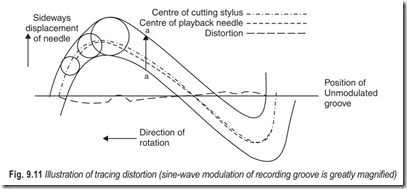
The stylus will be displaced with a signal, from the unmodulated position and the cutting face is at an acute angle to the direction of the groove. Thus the width of the groove is not uniform. This is illustrated in Fig. 9.11, which shows a sine-wave groove, very much magnified.
The width of the groove in the direction a–a always corresponds to the full width of the cutting edge of the stylus. The true width of the groove, that is, the width at right-angles to its length, depends on the angle between the modulated groove and the direction of the unmodulated groove, and will be smaller for greater values of this angle. The true width of the groove is the same as the width of the cutting edge only at the peaks of the sine wave.
If distortion is to be avoided, the sideways movement of the playback stylus should reproduce exactly the movement of this cutting stylus. The circles in Fig. 9.11 represent the point of the pick-up stylus as it rests in the groove during playback, and the centres of these circles should therefore lie on the line traced by the centre of the cutting stylus. The figure shows that this condition is not fulfilled: the dotted line traced by the centre of the pick-up stylus is not the same as the chain line traced by the centre of the cutting edge. The amount of distortion resulting from this lack of coincidence depends on the difference between these two lines, measured parallel to a—a. There is no distortion at the peaks of the sine wave, nor in the unmodulated position.
Tracing distortion consists of odd harmonics. The distortion increases as the modulation becomes more spiky. Thus, it increases with the amplitude of modulation—one reason why constant-amplitude recording is necessary at low frequencies. It also increases with frequency, which is the reason for restricting the amount of treble boost used when recording. The distortion is also greater if the modulation is compressed, as it will be near the centre of the record.
PINCH EFFECT
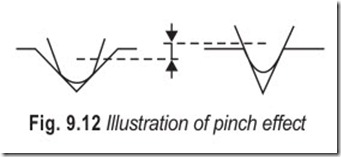
The sine-wave groove of Fig. 9.11 also illustrates the pinch effect which results from the varying width of a modulated groove on a monaural recording. Because of this varying width, the pick-up stylus will have to ride up and down as it traverses the groove, Fig. 9.12.
At the end of a microgroove recording , the maximum vertical movement may be as much as 11% of the maximum lateral displacement. The output of some pick-up heads varies slightly with this vertical movement so that pinch effect can be an additional source of distortion. As the needle has to move up and down twice during each cycle, the distortion is of even harmonic order.
NEEDLE-SCRATCH
As the pickup stylus traces the groove, the fine particles in the material of the disc cause the stylus to make small irregular movements. The voltage setup by these movement is amplified and is heard as needle scratch. The noise lies mainly between 2 and 10 kHz.
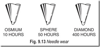
Needle scratch will be particularly bad when the diameter of the needle is too small for the groove. For good Fig. 9.13 Needle wear reproduction the stylus should rest on the two sides of the groove. If it rests right in the trough, it may ride up the walls, thus giving excessive scratch and additional distortion. If it rests on top of the groove only, it cannot follow the groove correctly, and there will then be a tendency for the stylus to skate across the record.
TRACKING ERROR
Another important difference between the making and replaying of discs is that the pickup stylus as it traverses the record does not follow the same path as the cutting stylus. The cutting stylus is set to move inwards in a straight line along a radius of the disc, whereas the pickup stylus must necessarily be mounted on a pivoted tonearm, and must cross the record in an arc of a circle. The playback stylus is thus not always held at right angles to the groove and the output will vary slightly. This effect is greater for large records, and can be reduced by using a longer pick-up arm.
TURNTABLE DRIVING SYSTEMS
It is essential that the mechanical driving systems of disc-playing equipment should be accurately made, especially with stereophonic equipment. Rotation of the turntable must be extremely steady. These requirements must necessarily be very severe if the mechanical system is to match the performance expected from the acoustical and electronic equipment.
In a high-quality installation, in which the loudspeaker is separate from the main chassis, the system can be mounted solidly to the motor board, and the motor board itself floated on rubber to ensure that no mechanical vibration is transmitted to the cabinet.
An unsuitable system can spoil the loudspeaker output in three objectionable ways : wow, flutter and rumble.
Wow and flutter are produced by variations in the speed of the turntable. Those variations occurring at low-frequencies are termed wow; flutter results from faster fluctuations. Slow variations can be caused by spindles and other rotating parts loosely mounted or off-centre, so that the wow resulting is heard at regular intervals. Unevenness of the drive, changes of friction (catching or slipping) and record slip can give rise to intermittent wow. Small irregularities are normally experienced when driving from a motor. Sudden changes in speed as little as 0.5% will be clearly noticeable as flutter when a long note is being played. A sufficiently steady speed is usually achieved by providing a heavy turntable, or some other moving part to act as a flywheel. Care should be taken to see that the speed-changing mechanism is not subject to undue wear. This can lead to wow or flutter after much use.
Rumble results because of the mechanical parts run noisily. These parts should run sufficiently quietly for no objectionable rumbling to be heard at full gain when there is no other input signal.
HOW ELECTRONIC CROSSOVERS HELP SPEAKERS & AMPS
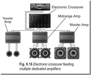
A crossover’s task is to direct a certain range of frequencies to a specific speaker or speakers. Where a passive crossover accomplishes this with a combination of low-pass and high-pass filters (usually placed in-line after the amplifier) an electronic crossover uses active circuitry feeding multiple dedicated amplifiers (see Fig. 9.16).
Advantages include greater flexibility, better transient response, lower distortion, and greater efficiency. The use of an electronic crossover in multi-amp component speaker systems is strongly
recommended.
Electronic crossovers let you vary the crossover point to precisely match the capabilities of the component speakers you’re using. You can also adjust the level of the signal to each of your amps, making it easy to boost the highs or lows or just go for a smooth, balanced response. Adjustability also lets you choose from a wider range of component speakers. If down the road you decide you want different speakers or amps, you’ll probably still be able to use your crossover with them.
Electronic crossovers let you vary the crossover point to precisely match the capabilities of the component speakers you’re using. You can also adjust the level of the signal to each of your amps, making it easy to boost the highs or lows or just go for a smooth, balanced response. Adjustability also lets you choose from a wider range of component speakers. If down the road you decide you want different speakers or amps, you’ll probably still be able to use your crossover with them.
EXERCISES
Descriptive Questions
1. Discuss the significance of a good speaker system for disc and tape reproduction.
2. What are the dissimilarities between recording and playback characteristics?
3. Explain the difference between standard, EP, and LP records.
4. Briefly explain the following
(a) tracing distortion (b) pinch effect
(c) tracking error (d) wow, flutter and rumble
Multiple Choice Questions
1. Dual systems using twin direct radiators are available as
(a) two completely separate units (b) an integral unit
(c) either (a) or (b) (d) both (a) and (b)
2. Crossover networks
(a) extend the frequency range (b) compress the frequency range
(c) reduce distortion (d) increase distortion
3. The velocity at which the stylus of magnetic-recording heads vibrates
(a) is directly proportional to the recording signal strength
(b) is exponentially related to the recording signal strength
(c) is inversely proportional to the recording signal strength
(d) is not related to the recording signal strength
4. Before recording, bass signal voltages from the recording amplifier are
(a) attenuated (b) boosted
(c) neither (a) nor (b)
5. Before recording, treble signals from the recording head are
(a) attenuated (b) boosted
(c) neither (a) nor (b)
6. The slope of the bass and treble sections of the recording characteristic depends on the degree of
(a) attenuation applied to the recording signal
(b) boost applied to the recording signal
(c) (a) or (b)
(d) (a) and (b)
7. Corrective networks are
(a) frequency selective (b) amplitude selective
(c) (a) or (b) (d) (a) and (b)
8. Tracking error can be reduced by using a
(a) medium sized pickup arm (b) Smaller pickup arm
(c) longer pickup arm
Fill in the Blanks
1. Tracking error is greater for records.
2. Wow and flutter are produced by variations in of the turntable.
3. Rumble results because mechanical parts noisily.
4. Needle scratch will be particularly if the diameter of the needle is for the groove.
5. Distortion due to pinch effect is of harmonic order.
6. Tracing distortion consists of harmonics.
ANSWERS
Multiple Choice Questions
|
1. (c) |
2. (a) |
3. (a) |
4. (a) |
5. (b) |
6. (c) |
|
7. (a) |
8. (c) |
Fill in the Blanks
|
1. large |
2. speed |
3. run |
|
4. bad, too small |
5. even |
6. odd |
