Thyristor Speed Control of Separately-excited D.C. Motor
In Fig. 30.32, the bridge rectifier converts a voltage into d.c. voltage which is then applied to the armature of the separately-excited d.c. motor M.
As we know, speed of a motor is given by
If F is kept constant and also if a is neglected, then, N µ V µ volt- age across the armature. The value of this voltage furnished by the recti- fier can be changed by varying the fir- ing angle a of the thyristor T with the help of its contol circuit. As a is in creased i.e., thyristor firing is delayed
more, its conduction period is reduced and, hence, armature voltage is decreased which, in turn, decreases the motor speed. When a is decreased i.e., thyristor is fired earlier, conduction period is increased which increases the mean value of the voltage applied across the motor armature. Consequently, motor speed is increased. In short, as a increases, V decreases and hence N decreases. Conversely, as a decreases, V increases and so, N increases. The free-wheeling diode D connected across the motor provides a circulating current path (shown dotted) for the energy stored in the inductance of the armature winding at the time T turns OFF. Without D, current will flow through T and bridge rectifier, prohibiting T from turning OFF.
Thyristor Speed Control of a D.C. Series Motor
In the speed control circuit of Fig. 30.33, an RC network is used to control the diac voltage that triggers the gate of a thyristor. As the a.c. supply is switched ON, thyristor T remains OFF but the capacitor C is charged through motor armature and R towards the peak value of the applied a.c. voltage. The time it takes for the capacitor voltage VC to reach the breakover voltage of the diac*
depends on the setting of the variable resistor T. When VC becomes equal to the breakover voltage of diac, it conducts and a triggering pulse is applied to the thyristor gate G. Hence, T is turned ON and allows current to pass through the motor. Increasing R delays the rise of VC and hence the breakover of diac so that thyristor is fired later in each positive half cycle of the a.c. supply. It reduces the conduction angle of the thyristor which, consequently, delivers less power to the motor. Hence, motor speed is reduced.
If R is reduced, time-con- stant of the RC network is de- creased which allows VC to rise to the breakover voltage of diac more quickly. Hence, it makes the thyristor fire early in each positive input half-cycle of the supply. Due to increase in the conduction angle of the thyristor, power delivered to the motor is increased with a subsequent in- crease in its speed. As before D is the free-wheeling diode which provides circulating current path for the energy stored in the in- ductance of the armature winding.
Full-wave Speed Control of a Shunt Motor
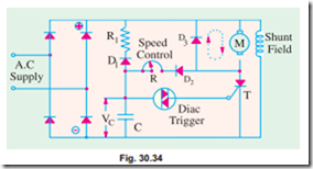
Fig. 30.34 shows a circuit which provides a wide range of speed con- trol for a fractional kW shunt d.c. motor. The circuit uses a bridge cir- cuit for full-wave rectification of the a.c. supply. The shunt field winding is permanently connected across the output of the bridge circuit. The armature voltage is supplied through thyristor T. The magnitude of this
voltage (and hence, the motor speed) can be changed by turning TON at different points in each half- cycle with the help of R. The thyristor turns OFF only at the end of each half-cycle. Free-wheeling diode D3 provides a circulating current path (shows dotted) for the energy stored in the armature winding at the time T turns OFF. Without D3. This current would circulate through T and the bridge rectifier thereby prohibiting T from turning OFF.
At the beginning of each half-cycle, T is the OFF state and C starts charging up via motor armature, diode D2 and speed-control variable resistor R (it cannot charge through R1 because of reverse- biased diode D1). When voltage across C i.e., VC builds up to the breakover voltage of diac, diac conducts and applies a sudden pulse to T thereby turning it ON. Hence, power is supplied to the motor armature for the remainder of that half-cycle. At the end of each half-cycle, C is discharged through D1, R1 and shunt field winding. The delay angle a depends on the time it takes VC to become equal to the breakover voltage of the diac. This time, in turn, depends on the time-constant of the R- C circuit and the voltage available at point A. By changing R, VC can be made to build-up either slowly or quickly and thus change the angle a at will. In this way, the average value of the d.c. voltage across the motor armature can be controlled. It further helps to control the motor speed because it is directly proportional to the armature voltage.
Now, when load is increased, motor tends to slow down. Hence, Eb is reduced. The voltage of point A is increased because it is equal to the d.c. output voltage of the bridge rectifier minus back
e.m.f. Eb. Since VA increases i.e., voltage across the R-C charging circuit increases, it builds up VC more quickly thereby decreasing which leads to early switching ON of T in each half-cycle. As a result, power supplied to the armature is increased which increases motor speed thereby compensating for the motor loading.
Thyristor Speed Control of a Shunt Motor
The speed of a shunt d.c.motor (upto 5 kW) may be regulated over a wide range with the help of the full-wave rectifier using only one main thyristor (or SCR) T as shown in Fig. 30.35. The firing angle a of T is adjusted by R1 thereby controlling the motor speed. The thyristor and SUS (silicon unilateral switch) are reset (i.e., stop conduction) when each half-wave of voltage drops to zero.
Before switching on the supply, R1 is increased by turning it in the counter-clockwise direction. Next, when supply is switched ON, C gets charged via motor armature and diode D1 (being forward bi- ased). It means that it takes much longer for VC to reach the breakdown voltage of SUS* due to large time constant of R1- C network. Once VC reaches that value, SUS conducts suddenly and triggers T into conduction. Since thyristor starts conducting late (i.e., its a is large), it furnishes low voltage to start the motor. As speed selector R1 is turned clockwise (for less resistance), C charges up more rapidly (since time constant is decreased) to the breakover voltage of SUS thereby firing T into conduction earlier. Hence, average value of the d.c. voltage across the motor armature increases thereby increasing its speed.
While the motor is running at the speed set by R1, suppose that load on the motor is increased. In that case, motor will tend to slow down thereby decreasing armature back e.m.f. Hence, poten- tial of point 3 will rise which will charge C faster to the breakover voltage of SUS. Hence, thyristor will be fired earlier thereby applying greater armature volt- age which will return the motor speed to its desired value. As seen, the speed is automatically regulated to offset changes in load.
The function of free-wheeling diode D2 is to allow dissipation of energy stored in motor armature during the time the full-wave rectified voltage drops to zero between half-cycles. If D2 is not there, then decreasing armature current during those intervals would be forced to flow through T thereby preventing its being reset. In that case, T would not be ready to be fired in the next half-cycle.
Similarly, towards the end of each half cycle as points 1 and 5 decrease towards zero potential, the negative going gate G turns SUS on thereby allowing C to discharge completely through SUS and thyristor gate-cathode circuit so that it can get ready to be charged again in the next half-cycle.
Thyristor Speed Control of a Series D.C. Motor
Fig. 30.36 shows a simple circuit for regulating the speed of a d.c. motor by changing the average value of the voltage applied across the motor armature by changing the thyristor firing angle a. The trigger circuit R1 – R2 can give a firing range of almost 180°. As the supply is switched on, full d.c. voltage is applied across R1 – R2. By changing the variable resistance R2, drop across it can be made large enough to fire the SCR at any desired angle from 0° – 180°. In this way, output voltage of the bridge rectifier can be changed con- siderably, thus enabling a wide-range control of the motor speed. The speed control can be made somewhat smoother by joining a capacitor C across R2 as shown in the figure.
Necessity of a Starter
It has been shown in Art 29.3 that the current drawn by a motor armature is given by the relation
![]() where V is the supply voltage, Eb the back e.m.f. and Ra the armature resistance.
where V is the supply voltage, Eb the back e.m.f. and Ra the armature resistance.
When the motor is at rest, there is, as yet, obviously no back e.m.f. developed in the armature. If, now, full supply voltage is applied across the stationary armature, it will draw a very large current because armature resitance is relatively small. Consider the case of a 440- V, 5 H.P. (3.73 kW) motor having a cold armature resis- tance of 0.25 W and a full-load current of 50 A. If this motor is started from the line directly, it will draw a starting current of 440/0.25 = 1760 A which is 1760/50 = 35.2 times its full-load current. This excessive cur- rent will blow out the fuses and, prior to that, it will damage the commutator and brushes etc. To avoid this happening, a resistance is introduced in series with the armature (for the duration of starting period only, say 5 to 10 seconds) which limits the starting current to a safe value. The starting resistance is gradually cut out as the motor gains speed and develops the back e.m.f. which then regulates its speed.
Very small motors may, however, be started from rest by connecting them directly to the supply lines. It does not result in any harm to the motor for the following reasons :
1. Such motors have a relatively higher armature resistance than large motors, hence their starting current is not so high.
2. Being small, they have low moment of inertia, hence they speed up quickly.
3. The momentary large starting current taken by them is not sufficient to produce a large disturbance in the voltage regulation of the supply lines.
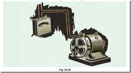
In Fig. 30.37 the resistance R used for starting a shunt motor is shown. It will be seen that the starting resistance R is in series with the armature and not with the motor as a whole. The field winding is connected directly across the lines, hence shunt field current is independent of the resistance R. If R wes introduced in the motor circuit, then Ish will be small at the start, hence starting torque Tst would be small (∵ Ta µ F Ia) and there would be experienced some difficulty in starting the motor. Such a simple starter is shown diagramatically in Fig. 30.38.
The face-plate box type starters used for starting shunt and compound motors of ordinary industrial capacity are of two kinds known as three- point and four-point starters respectively.
Three-point Starter
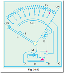
The internal wiring for such a starter is shown in Fig. 30.39 and it is seen that basically the connections are the same as in Fig. 30.37 except for the additional protective devices used here. The three terminals of the starting box are marked A, B and C. One line is directly connected to one armature terminal and one field terminal which are tied together. The other line is connected to point A which is further connected to the starting arm L, through the overcurrent (or overload) re- lease M.
To start the motor, the main switch is first closed and then the starting arm is slowly moved to the right. As soon as the arm makes contact with stud No. 1, the field circuit is directly con- nected across the line and at the same time full starting resistance R, is placed in series with the armature. The starting current drawn by the armature = V/(Ra + Rs) where Rs is the starting
resistance. As the arm is further moved, the starting resistance is gradually cut out till, when the arm reaches the running position, the resistance is all cut out. The arm moves over the various studs against a strong spring which tends to restore it to OFF position. There is a soft iron piece S attached to the arm which in the full ‘ON’ or running position is attracted and held by an electromagnet E energised by the shunt current. It is variously known as ‘HOLD-ON’ coil, LOW VOLTAGE (or NO-VOLTAGE) release.
It will be seen that as the arm is moved from stud NO. 1 to the last stud, the field current has to travel back through that portion of the starting resistance that has been cut out of the armature cir- cuit. This results is slight decrease of shunt cur- rent. But as the value of starting resistance is very small as compared to shunt field resistance, this slight decreases in Ish is negligible. This defect can, however, be remedied by using a brass arc which is connected to stud No. 1 (Fig. 30.40). The field circuit is completed through the starting resistance as it did in Fig. 30.39.
Now, we will discuss the action of the two protective devices shown in Fig. 30.39. The normal function of the HOLD-ON coil is to hold on the arm in the full running position when the motor is in normal operation. But, in the case of failure or disconnection of the supply or a break in the field circuit, it is de-energised, thereby releasing the arm which is pulled back by the spring to the OFF position. This prevents the stationary armature from being put across the lines again when the supply is restored after temporary shunt down. This would have happened if the arm were left in the full ON position. One great advantage of connecting the HOLD-ON coil in series with the shunt field is that, should the field circuit become open, the starting arm immediately springs back to the OFF position thereby preventing the motor from running away.
The overcurrent release consists of an electromagnet connected in the supply line. If the motor becomes overloaded beyond a certain predetermined value, then D is lifted and short circuits the electromagnet. Hence, the arm is released and returns to OFF position.
The form of overload protection described above is becoming obsolete, because it cannot be made either as accurate or as reliable as a separate well-designed circuit breaker with a suitable time element attachment. Many a times a separated magnetic contactor with an overload relay is also used.
Often the motors are protected by thermal overload relays in which a bimetallic strip is heated by the motor current at approximately the same rate at which the motor is itself heating up. Above a certain temperature, this relay trips and opens the line contactor, thereby isolating the motor from the supply.
If it is desired to control the speed of the motor in addition, then a field rheostat is connected in the filed circuit as indicated in Fig.30.39.The motor speed can be increased by weakening the flux (Œ N µ I/F). Obviously, there is a limit to the speed increase obtained in this way, although speed ranges of three to four are possible. The connections of a starter and speed regulator with the motor are shown diagrammatically in Fig. 30.41. But there is one difficulty with such an arrangement for speed control. If too much resistance is ‘cut in’ by the field rheostat, then field current is reduced very much so that it is unable to create enough electromagnetic pull to overcome the spring tension. Hence, the arm is pulled back to OFF position. It is this undesirable feature of a three-point starter which makes it unsuitable for use with variable-speed motors. This has resulted in widespread application of four-point starter discussed below.
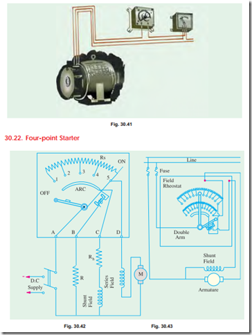
Such a starter with its internal wiring is shown, connected to a long-shunt compound motor in Fig. 30.42. When compared to the three-point starter, it will be noticed that one important change has been made i.e., the HOLD-ON coil has been taken out of the shunt field circuit and has been connected directly across the line through a protecting resistance as shown. When the arm touches stud No. 1, then the line current divides into three parts (i) one part passes through starting resistance Rs, series field and motor armature (ii) the second part passes through the shunt field and its field rheostat Rh and (iii) the third part passes through the HOLD-ON coil and current-protecting resistance R. It should be particularly noted that with this arrangement any change of current in the shunt field circuit does not at all affect the current passing through the HOLD-ON coil because the two circuits are independent of each other. It means that the electromagnetic pull exerted by the HOLD-ON coil will always be sufficient and will prevent the spring from restoring the starting arm to OFF position no matter how the field rheostat or regulator is adjusted.
Related posts:
Incoming search terms:
- speed control of dc motor using thyristor
- speed control of dc motor by thyristor
- project on speed control of dc motor using thyristor
- speed control of dc shunt motor using thyristor
- speed control of dc motor using scr pdf
- speed control of dc motor using scr
- speed control of DC shunt motor using SCR
- DC motor speed control by thyristor
- drawing the schematic diagram of dc motor speed control by thyristor
- speed control of dc motor using thyristor pdf
- thyristor speed control of dc motor
- thyristor control of dc motor
- speed control of dc motor using thyristor ppt
- thyristor control of dc motor circuit diagram
- to study thyristor control of dc motor and draw the circuit diagram
- dc motor speed control using scr
- dc motor speed control using scr circuit diagram
- speed control of dc motor using thyristor circuit diagram
- speed control of dc motor using scr project report
- dc motor speed control circuit using scr
- to make the connection determine the parameters and speed control of dc motor by thyristor/dc drive
- thyristor speed control of dc shunt motor
- To make the connections determine the parameters and speed control of Dc motor by thyristor/Dc drive
- schematic diagram of DC motor speed control by thyristor
- speed control of dc series motor using scr
- dc motor speed control using thyristor
- thyristor speed control
- dc motor control using scr
- drawing the schematic diagram of d c motor speed controlled by thyristor
- speed control of dc motor by using thyristor
- draw the schematic diagram of A C motor speed control using SCR
- Drawing the schematic diagram of D C motor speed control by Thyristor
- to make the connection determine the parameters and speed control of dc motor by thyristor
- speed control using thyristor
- diagram of dc motor speed control by thyristor
- Speed Control of DC Motor Using TRIAC
- speed control of dc motor using single phase full converter
- rectifier control of dc series motor
- thyristor speed control of dc series motor
- speed control of dc motor using scr ppt
- drawing the schematic diagram of D C motor speed controled by thyristor
- dc motor speed control by thyristor diagram
- thyristor speed control field
- Speed control of motor using scr
- speed control of dc series motor using thyristor
- speed control of dc motor by Scr
- speed control of dc motor using triac pdf
- speed control of dc motor by using scr
- thyristor controlled dc motor drive
- speed control of dc shunt motor using phase controlled rectifier


