VALVE SEAT INSERTS
Some engines have hard steel valve seat inserts for the exhaust valves while others are equipped with these inserts for both intake and exhaust
valves.
Seat inserts, especially f or exhaust valves, occa sionally require replacement. Hard driving with a badly leaking exhaust valve may burn the exhaust seat beyond repair.
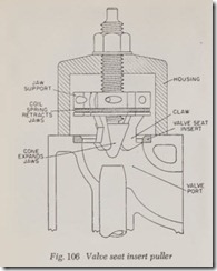
The insert is readily removed with the puller shown in Fig. 106. The tool consists of an inverted cup-like housing in which is mounted three claws or jaws which are carried in a jaw support threated on the lower end of the screw. The posi tion of the claws can be moved up or down by turning the nut. The claws are expanded against the sides of the valve port by turning the screw while holding the nut stationary.
To pull out the insert, the device should be ad justed so that the edges of the claws contact the valve port firmly about )6” below the insert. Then pull the claws upward by turning the nut while at the same time turn the screw so that the claws will be certain to grip the insert properly. Then keep on turning the nut until the insert is removed.
If such an insert puller is not available, the insert can be broken and removed in two pieces. Using a drill somewhat smaller than the insert, drill two holes at opposite sides of the insert but be careful not to drill all the way through the seat as damage to the block (or head) will result. Use a sharp cold chisel to cut through the holes and thus split the seat in two halves.
Af ter the seat has been removed, clean the counterbore in the block so that th e new seat, when installed, will sit squarely in the recess. Note also, that dirt in the recess will prevent proper conduction of heat from the seat to the b lock.
The seat is slightly larger in diameter than the recess. Therefore, to install a new seat, pack it in “dry ice” for at least 15 minutes in order to con tract it. Line the cold seat up squar ely with the recess and use a hammer and block of wood to force it in place.
If a standard size insert fits too loose, the recess should be enlarged by counterboring to fit an oversize seat. Check the diameter of the oversize seat before counterboring. For best r esults, the insert should be .003″ larger than the diamet er of the recess when both are at the same temperature (room temperature) although an insert which is anywhere from .002” to .004″ larger is considered satisfactory.
Valve seat inserts are so hard that when they need rcfacing a high-speed grinding stone should be used. They cannot be ground satisf actorily by lapping with valve grinding compound .
HYDRAULIC VALVE LIFTERS
The purpose of the hydraulic valve lifter (or tappet) is to provide perfect adjustm ent at all times between the valve stem and th e lifter on L head engines and between the rocker arm and the
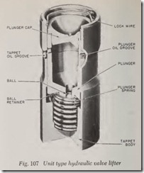
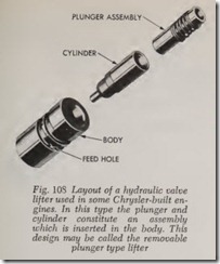
valve stem on overhead valve engines. The oil operated hydraulic lifter provides this perfect ad justment automatically. Fig. 107 illustrates the unit lifter while Fig. 108 illustrates a Chrysler lifter in which the plunger and the cylinder consti tute an assembly which is inserted in the lifter body.
An ideal hydraulic lifter would be one which keeps in constant contact with the valve stem or push rod regardless of how th e valve stem or push rod and cylinder block expand and contract under variations in temperature. With constant contact, the clearance is always zero when the valve is closed.
with this ideal of zero clearance, valve noise is reduced to a minimum . During th e valve opening process, the lifter is already in contact with the stem and therefore the noise of contact is elimi nated. During the closing process, the valve comes gradually to rest on its seat instead of hitting it with a sharp noisy blow.
This zero clearance obviously cannot be ob tained with screw-adjusted valve lifters but is obtained with automatically adjusted hydraulic lifters. This statement, how ever, should not be construed as unqualified prais e for the hydraulic lifter. Both the hydraulic lifter and the screw-ad justed lifter have their advantages and their dis advantages.
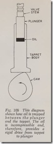
The principle of the hydraulic lifter is easy to understand. Fig. 109 is a simplified diagram in which a plunger is slidably mounted in a tappet. At th e base of the plunger is a small chamber filled with oil. Since oil (and all other liquids) is practically incompressible, the oil trapped in this chamber provides a positive drive from cam to valve stem. When the valve is being opened by the cam, the drive is just as positive as it would be if a steel spacer were substituted for the oil. It is a mistake to assume that the oil gives a cushioning effect. On the contrary, the oil provides a perfectly rigid drive.
Although the plunger diameter, Fig. 109, has a clearance of a mere fraction of a thousandth of an inch, it is obvious that there must be some slight leakage between the plunger and its bore when ever the valve is open because of the high pres sure of the valve spring which pushes down on the plunger.
To compensate for this leakage, oil is supplied under pressure, Fig. 110, to the oil chamber be neath the plunger.
With engine running and the valve momentarily resting on its seat, its stem is not exerting pressure on the plunger. Therefore the oil pressure in the gallery is more than enough to force the ball eheek valve off of its seat so that replacement oil may be foreed into the oil ehamber.
However, just as soon as the eam starts to open the valve, the valve stem presses on the plunger whieh in turn presses on th e oil. This oil pressure forecs the ball eheek valve tight into its seat. Then the oil, trapped in the oil ehamber, rigidly trans mits th e upwa rd tappet motion to the plunger whieh transmits it to the valve stem and in this way the valve is opened. There is a rather light spring between the top of the plunger and the tappet. It pushes upward on the plunger and downward on the tappet so that the plunger is always in eontaet with the valve stem and of eourse the tappet is always in contaet with the eam.
We are now in a position to explain how the automatic tappet adjustment is obtained regard less of wh ether the valve parts have been length ened by a hot engine or shortened by a cold
engine.
The oil ehamber ought to be ealled an adjusting ehamber. To explain how the ehamber works, let us assume that the engine is eold but that it was thoroughly warm when it was last used.
The valve stems have eontraeted during the eooling off period. During contraction, the plunger springs pushed the plunger upward, thus keeping them in constant eontaet with their valve stems. The upward movement of the plungers therefore has increased the volume of the adjust ing chambers and th ese chambers are now not completely filled with oil. In other words the valves arc out of adjustment on the loose side.
However, when the engine is started it only re quires a few seeonds for the oil pressure to deliver oil to the adjusting chambers to fill them up and thus provide the necessary rigid drive from tappet
to plunger.
As the engine warms up, the valve stems ex pand lengthwise, the natural leakage past the plungers permitting them to do so. The leakage is always enough so that there is no danger of a valve being held off of its seat because of rapid valve stem expansion. Actually the leakage is more than adequate.
The correct leakage rate is carefully determined when the hydraulic lifter is manufactured. And it is most important to realize that the leakage rate, although small, is deliberately designed to keep the valve adjustment on the loose side. But this tendency toward looseness is prevented by the engine oil pump which is ready to fill the oil chamber whenever the valve is closed. Therefore the valves are always in perfect adjustment-that is the plungers are always in contact with their valve stems, except for the first few seconds after the engine is started from cold.
The leakage rate is determined by the amount of clearance between the plunger and the plunger bore. The desired clearance is a fraction of a thousandth of an inch and this clearance must be closely approximated on all lifters made for a given model of engine. Therefore after the plungers and bores have been manufactured as accurately as possible they are classified into a series of sizes from a trifle small to a trifle large. Small plungers are assembled to small bores, large to large, and likewise for the sizes in between. In this way satisfactory uniform clearance is ob tained in all plungers and bores even though individual plungers and bores may vary in size by a small amount. This “selective” fitting of plungers and bores explains why it is important during repair work that a given plunger always be re turned to its own bore.
If the plunger clearance is too great, either because of wear or because of mismating of plunger and bore, the oil may leak away faster than it is supplied to the oil chamber. The cham ber will never be full and therefore the lifter will be noisy .
If the plunger is too tight in its bore because of mismating, the plunger action may be sluggish and noisy lifters may result. Or more likely, the leakage rate will be so slow that the valve is held off its seat when it should be closed.
Most engines have an oil passage drilled the length of the crankcase. This passage is often called a gallery (or galley) and is used to dis tribute oil from th e engine’s oil pump to drilled passag es leading to the hydraulic valve lifters as well as to the main and camshaft bearings.
Hydraulic valve lifters can be classified as being the unit type and removabl e plunger type. In the unit type, Fig. 107, the plunger is installed di rectly in the lifter body. Not e that there is an oil groove in both the body and plunger. Oil under pressure is sent from the gall ery through the tappet oil groove, tappet oil hole, plunger oil groove, plunger oil hole, past ball check valve to plung er oil chamber.
With the removable plung er type, Fig. 110, the plung er is mounted in a plun ger cylinder which is installed in the tappet body. The plunger cylinder assembly is removed as a unit by simply pulling it out of the body.
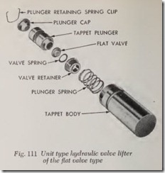
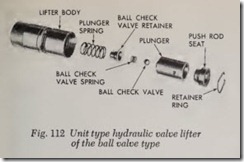
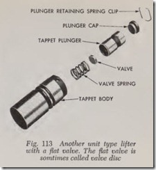
Other examples of the unit type lifter are shown in Figs. 111,112,113.
Hydraulic Lifter Troubles
The most frequent causes of hydraulic valve lifter troubles are dirty oil or failure to change the oil filter at suggested intervals. When these causes are eliminated, the b·ouble will ‘generally correct itself without costly disassembly.
The easiest method for locating a noisy valve lifter is by the use of a piece of garden hose about 4 feet long. Place one end of the hose near each valve in progression and listen through the other end. In this manner the sound is localized, making it easy to determine which lifter is at fault.
Another method is to place a finger on the valve spring retainer. If the lifter is not functioning properly, a distinct shock will be felt when the valve returns to its seat.In most cases where noise exists in one or more lifters, all lifter units should be removed and cleaned. If dirt, varnish or carbon is found to exist in one unit, it more than likely exists in all the units.
The oil level in the oil pan should never be above the “Full” mark on the dipstick nor below the “Add Oil” mark. Either condition could be responsible for noisy valve lifters.
Oil Level Too High-If the oil level is too high it is possible that the connecting rods can dip into the oil when the engine is running and create foaming. This foam (air mixed with oil) is fed to the hydraulic lifter by the oil pump, and the air gets into the lifters, causing them to go flat and allow the valves to seat noisily.
Oil Level Too Low-Low oil level may allow the oil pump to take in air which, when fed to the lifters, causes them to lose length and allows the valves to seat noisily. Any leaks on the intake side of the oil pump through which air can be drawn will create the same lifter action. When the lifter noise is due to aeration, it may be intermittent or constant, and it will always cause more than one lifter to be noisy. When the oil level and leaks have been corrected, the engine should be run at a fast idle speed for sufficient time to allow all of the air inside of the lifter to be worked out.
Hydraulic Lifter Noises
It should be remembered that worn valve guides or cocked valve springs arc sometimes mistaken for noisy lifters. If such is the case, the noise in all probability will be dampened by ap plying side thrust with your thumb on the valve spring. If the noise is not appreciably reduced, it can then be assumed that the noise is in the hydraulic lifter.
Servicing Hydraulic Lifters
Inasmuch as the removable plunger type lifters have not been in use for quite a number of years, the following discussion is concerned only with the unit type lifter.
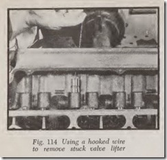
With this type lifter, Figs. 107 to 113, the units may be lifted out with the fingers. However, if the lifter is stuck in its guide due to varnish or gum substances, use pliers with taped jaws or pull it out with a hooked wire as shown in Fig. 114.
If there is a ring of carbon on the guide just above the top of the lifter it will be necessary to remove the carbon before the lifter can be taken out. Soften up the carbon with a solvent and remove with a stiff bristle brush.
As shown in the illustrations, these units can be completely disassembled. The first step is to re move the lock wire by prying it out of its groove with a small screwdriver or awl. Hold the thumb over the opening to prevent the lock wire from flying away when it comes loose.
If there is a rim of carbon at the upper end of the plunger bore, soak the unit in solvent (lacquer thinner is recommended) and remove the carbon with a stiff bristle brush. The carbon will interfere with the removal of the plunger.
Next turn the unit upside down and strike it against the palm of the hand to force the assembly out. Do this carefully so that the parts, when they do come out, do not scatter. The ball check valve is especially likely to roll out of sight. If pounding the lifter against the palm fails to break the plunger loose, pound it on a block of wood.
Be careful not to mix up plungers and bodies.
To avoid this possibility, disassemble and assem ble them one at a time. Wash the parts in solvent and then examine them for defects such as scratches, pits and dents. If any are found, discard the complete unit.
Insert the bare plunger in the body. It should move smoothly when pushed gently with a finger. In some cases it will even fall of its own weight if the unit is held vertical. If there is extra resistance, discard the assembly.
To check for leakage, make an air compression test. To do this, turn the plung er upside down and install the ball check valve and the retainer but do not install the spring. While holding the plunger assembly with one hand, slide the body down over the plunger. Still holding the unit upside down, pump the plunger with the little finger or with a screwdriver. If the plunger bounces, the unit is all right. On the other hand if it docs not bourice, examine the ball valve or Bat valve for damage. If a ball valve is used, examine it for a Bat spot and, if one is found, install a new ball of the same size. However, if the ball or flat valve is in good condition and the compression is poor, the plunger leaks and therefore the complete unit should be discarded.
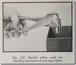
The tool shown in Fig. 115 is also used to check the compression of unit type lifters; it is used in the same manner described for the removable plunger type.
In testing lifters of this type, the container must be deep enough to completely immerse the lifter assembly. Fill the container with clean kerosene. Remove the cap from the plunger and submerge the lifter. Allow the cylinder to fill with kerosene. Then remove the lifter and replace the cap.
Then, with the tool applied to the lifter as shown in Fig. 115, check the leakdown by com pressing the tool handles. If the plunger collapses almost instantly, disassemble the unit, clean it again and retest. If the lifter still does not function satisfactorily, install a new unit, being sure to test the new one before installing it in the engine.
Assembling Lifters
To assemble, turn the plunger upside down and install the check valve, its retainer and plunger spring. Slip the lifter body on the plunger assem bly. Turn the assembly over and install the lock wire, being sure it snaps into its groove in the lifter body. A discarded plunger or a special tool for the purpose may be used to press the plunger down in order to insert the lock wire.
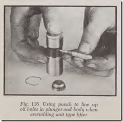
If neither a special tool nor a discarded plunger is available, the following method may be used. Assemble the parts as before. Then slide the body down over the plunger. Take a small piece of wire (a paper clip will do) or a small punch, Fig. 116, and insert it in the oil hole in the body. Press the plunger down slowly almost as far as it will go with one finger of the other hand until the wire or punch slips into the oil hole in the plunger. This locks the plunger. Install the plunger cap. Insert the open end of the lock ring in the lifter body. Then force the opposite side of the lock ring into the groove with a small, blunt tool such as a screwdriver.
It is recommended that lifters of this type be filled with engine oil before replacing them in the engine. However, many mechanics rarely take the time to do this. In other words, they are installed dry and then filled by the oil pressure supplied by the idling engine. Apparently no harm is done by neglecting to fill the lifters. However, as there is some risk of scuffing, at least dip the plungers in engine oil before installing them in the engine.
A better method, which is quick and easy, is to put the dry lifter in a pan of engine oil and pump the plunger until the lifter is reasonably full. The oil level in the pan, of course, should be high enough to cover the oil hole in the side of the lifter body. The plunger should be pumped just a few strokes until the plunger travel becomes a mini mum. It is possible to pump the plunger until it is rigid.
