AM/FM TUNERS
The r.f. tuner selects the band, and amplifies the incoming signal to maintain a good signal to noise ratio. The gain is controlled by a.g.c. to suit the input signal strength. It converts the r.f. into i.f. by mixing it with the local oscillator to feed it into the first i.f. amplifier. It blocks the antenna pick-up signals in the i.f. range and prevents them from entering the receiver. It isolates the local oscillator signals from the antenna, due to the r.f. amplifier acting as a buffer, preventing radiation and interference to other receivers. It also rejects the image frequencies by means of r.f. selective circuits.
AM/FM BASICS
A radio frequency wave may be modulated in accordance with intelligence to be transmitted by varying either the amplitude or the frequency of the r.f. oscillations. In an amplitude modulated wave, the amplitude of the r.f. oscillation is varied in accordance with the intelligence to be transmitted, while the frequency of the oscillations is maintained constant. The intelligence to be transmitted usually consists either of an audio modulating signal with the frequencies in the range 20 Hz to 20 kHz or a video modulating signal, with frequencies from dc to several megahertz. The modulating signal is superimposed upon the radio frequency carrier by applying both to a nonlinear impedance (e.g. the modulator). When this is done, the modulating and carrier frequencies beat together, or hetrodyne, to produce additional frequencies equal to the sum and the difference of the applied frequencies. The resulting modulated wave, therefore consists of the original carrier frequency, various sum frequencies which are collectively known as the upper sideband, and various difference frequencies which are collectively known aslower sideband. The total bandwidth of the modulated wave is twice the value of the highest modulating frequency. For example, if the highest modulating frequency is 15 kHz, the total bandwidth of the two sidebands is 30 kHz and this bandwidth must be passed by all transmitting and receiving circuits.
It is these sideband frequencies that carry the intelligence in an amplitude modulated wave. When an r.f. carrier is modulated by many audio frequencies, such as in speech or music, the sidebands consist of a band of frequencies above and below the carrier frequency. The width of this band is determined by the highest modulating frequency. For this reason all a.m. signals must have an available bandwidth equal to the highest frequency to be reproduced. Since a.m. transmitting stations are only 10 kHz apart from each other, they are necessarily limited to 10 kHz bandwidth. Therefore, the highest audio frequency possible to be transmitted by a.m. radio is 5 kHz.
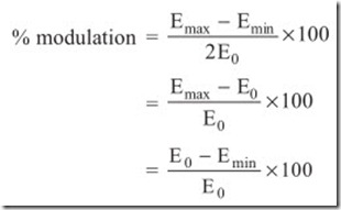
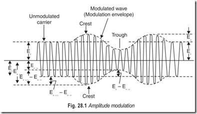
The extent by which the amplitude of the modulated wave is varied by the modulating signal is called the degree of amplitude modulation. Where am is the maximum amplitude of the modulating signal as shown in Fig. 28.1, and Eo is the amplitude of the unmodulated carrier (equal to average amplitude of the modulated wave or modulation envelope). The degree of modulation is usually expressed in per cent, as follows:
For any kind of modulating signal, sinusoidal or other
For a sinusoidal modulating signal, where the modulation is symmetrical about the carrier, the modulation percentage is also given by the relation:
where Emax , Emin , and Eo are the maximum, minimum, and average amplitude of the modulated wave (envelope).
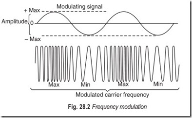
In frequency modulation, the intantaneous frequency of the radio frequency oscillations is varied in accordance with the modulating signal (intelligence) to be transmitted while the amplitude of the oscillations is maintained constant. This is illustrated in Fig. 28.2.
The number of times (per second) that the instantaneous frequency is varied about the average or carrier frequency is called the modulating frequency, while the amount of frequency variation from the average (carrier frequency) is called the frequency deviation. The frequency deviation is proportional to the amplitude of the modulating signal. For example, a 1000 Hz sound wave of a certain amplitude could be transmitted by frequency modulating a 10 MHz carrier between 9.9 MHz and 10.1 MHz, 1000 times each second. If the frequency of the audio signal (pitch of the sound wave) is increased to 2000 Hz, the instantaneous frequency of the carrier would now be varied between the same frequency limits 2000 times per second.
However, if the amplitude of the audio signal doubles, the instantaneous carrier frequency would be varied through twice the frequency range, that is, between 9.8 and 10.2 MHz. The modulating frequency would be left unchanged is this case.
There are several terms and concepts that are basic to the understanding of FM in general. Therefore, it is helpful to have a basic understanding of the meaning of each one.
One term which is generally misunderstood is deviation. Most people think of deviation as frequency swing. Deviation refers to the amount of percentage of modulation. It is the displacement of the carrier in kilohertz, and it is caused by the application of an audio modulating signal. Deviation is measured from the carrier centre to one extreme of the signal’s bandwidth. There is positive deviation as the carrier swings above its unmodulated frequency and negative deviation when the carrier swings below its unmodulated value. If the modulating signal is a sine wave the carrier will start from the unmodulated value and increase in frequency as the sine wave signal voltage becomes more positive. When the sine wave reaches maximum in the positive direction, the maximum carrier deviation is reached. As the sine wave heads back towards the zero line, the carrier frequency decreases until it once again reaches the centre or “at rest” point. When the audio sine wave polarity reverses the carrier begins to decrease in frequency. When the sine wave reaches the maximum negative value, the carrier is at the maximum negative deviation. If the modulating signal is a perfect sine wave, the negative and positive deviation percentages will be equal. If they are not equal, nonlinearity, or distortion, will be present in the audio at the receiver output.
Another frequently misinterpreted term is frequency swing, which is the total carrier displacement as measured from the maximum negative deviation to the maximum positive deviation. With sinusoidal modulating signals, the frequency swing is twice the deviation. Remember this difference. Deviation is the carrier displacement measured from the unmodulated carrier frequency to the maximum in one direction. The FCC (Federal Communications Committee) defines, 100 per cent f.m. modulation as plus or minus 75 kHz deviation. There is no real basis for this figure. It is an arbitrary standard.
Contrary to popular belief, the amount of deviation is not dependent upon the frequency of the modulating audio in a true f.m. system. The amount of deviation in an f.m. transmitter is determined largely by the intensity of the modulating signal. Amplitude—rather than frequency—determines this important parameter. In the FM system, the frequency of the audio signal determines the rate at which the carrier swings between the deviation limits. It will swing completely positive and then completely negative for each cycle of the modulating audio.
An a.m. station may only transmit audio frequencies upto 5000 Hz, while an f.m. broadcaster is allowed to transmit audio frequencies upto 15 kHz. If this higher limit were allowed to the a.m. broadcaster, a considerably smaller number of stations would be accommodated. The bandwidth of an a.m. signal is directly proportional to the frequency of the audio modulating signal.
The f.m. band is located in the low to medium region of the v.h.f. portion of the radio spectrum. This wide range of frequencies and the relative “isolation” of the band has proved to be both a blessing and a curse. On the one hand, the market was limited initially because of the technical complexity of the receiving equipment. On the other hand, though, the spectrum space allotted to f.m. provided the wide bandwidths necessary for quality sound transmission. It gave the medium exclusivity and a growing reputation for offering the best in recorded and, occasionally, live music.
Early tube type FM tuner were a real fright. Typical f.m. tuners of that era were quite inferior to today’s standards. Advanced engineering and the advent of solid-state circuits capable of operation in the v.h.f. region changed the FM scene considerably. By the early 60s, the FM tuner, and the few receivers then available, were relatively reliable pieces of equipment. The FM devices finally qualified for the main “high fidelity”.
It was about this time that all new record players were equipped with an extra audio channel and a stereo pick-up cartridge. In the early 60s, the FCC allowed a modification of the f.m. technical rules that permitted stereo broadcasting. But the commission stipulated that stereo transmissions had to be compatible with existing standards so that no program material would be lost to the listener equipped with only a monaural receiver. The system eventually approved met this requirement nicely.
In the stereo system adopted, monaural compatibility is accomplished by linearly mixing the left and right-channel audio signals to produce a sum labeled the L+R signal. A different signal, needed to regenerate the discrete left and right-channel signals from the L + R, is created by first inverting the phase of the right- channel signal 180 degrees and then mixing it with the left-channel signal. This action produces an L – R signal. The L – R signal is used to amplitude-modulate a suppressed subcarrier of 38 kHz. The result is an encoded, inaudible, stereo signal which is mixed with the L + R signal to decode the stereo components of the left and right-channels.
TUNERS
Tuners are available to receive a.m. or f.m. signals separately or in one combined unit. Some tuners provide for the preamplifier-equaliser function. These functions are provided because in some installations no other program material source other than the tuner is required. In other cases a separate preamplifier control is not as desirable as having all controls on the same panel with the tuning control. The performance of such a tuner preamplification-compensation system should not be expected to be as good as a top-quality separate control preamplifier, but the design of this arrangement usually provides as much quality as is usable for
a.m. or f.m. reception or other average pick-up.
Amplitude modulation reception is usually limited to a 10,000 Hz limit of frequency response or less because a.m. broadcast stations are separated only by this amount and reception of two nearly equal signals only 10 kHz apart will produce a strong 10 kHz beat note, which is unpleasant to sensitive ears if not filtered out. Frequency modulation tuners can provide a greater range of reproduction and high fidelity over the entire audible range, if all elements of the systems involved are designed, arranged, and operated to achieve maximum performance.
AM TUNERS
Amplitude modulation tuners covering the broadcast band from 500 to 1500 kHz, are usually of the superheterodyne type, having an r.f. preamplifier to reduce image interference, a first detector-oscillator to convert the signal frequency to a lower level—where there are better r.f. amplification conditions—a second detector to rectify or pick-off the sound signal from the carrier signal, and an audio amplifier and output arrangement to bring the signal to sufficient level to drive a basic audio amplifier or control unit of hi-fi type. In addition, there may be the usual control features, such as automatic volume control, noise limiting, and others.It is generally agreed that high fidelity reproduction entails a frequency response that is flat within ± 1 dB from 20 Hz to 20 kHz approximately, and with a harmonic-distortion (HD ) figure of less than 1 per cent at rated power output. Harmonic distortion and intermodulation distortion (IM) values usually have the same order of magnitude. However, there are certain types of system defects that cause IM distortion to increase much more rapidly than harmonic distortion as the power input is increased.
An a.m. tuner is a refined version of a conventional a.m. radio receiver, but without an audio amplifier and speaker. A hi-fi a.m. tuner differs from an ordinary a.m. tuner primarily in its greater bandwidth. A hi- fi unit also has certain minor refinements. In most cases, a hi-fi a.m. tuner is provided as a section of a hi-fi AM/FM receiver.
Most current model hi-fi AM tuners are solid-state. Solid-state design is usually on a transistor-for-tube basis, except for systems employing IC packages. Printed circuit construction is inevitably utilised. The superheterodyne configuration is universal, although design details vary considerably.
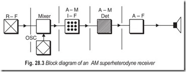
A superheterodyne receiver, illustrated in Fig. 28.3 is one in which the desired signal is mixed with a locally generated signal to produce an intermediate-frequency signal. The intermediate frequency signal is then amplified and detected to produce the audio frequency.
A typical arrangement utilises four transistors and a diode detector; two i.f. stages are used with no r.f. amplification (no pre-selection). In economy type designs, we may find that a single transistor does double duty by operating as an oscillator and converter. Integrated circuitry is used in the i.f. section by some manufacturers. Deluxe AM tuners are provided with at least one stage of pre-selection to improve selectivity and image rejection.
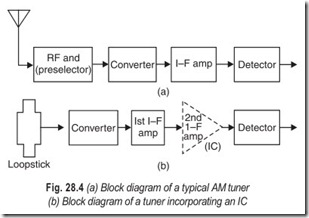
The block diagram of a typical a.m. tuner is shown in Fig. 28.4 (a). This arrangement employes a preselector stage (r.f. amplifier) a converter, an i.f. stage, and a diode detector. The tuning range is from 530 to 1620 kHz, no shortwave bands are provided. The converter stage has a single transistor that does double duty as an oscillator and mixer. On the other hand, some a.m. tuners use two transistors in this section—one transistor operates as an oscillator, and the other operates as a mixer. An external antenna is utilised.
Another arrangement for an AM tuner is shown in Fig. 28.4 (b). It includes two transistors, an integrated circuit, and a diode detector. No preselector is provided, and the converter stage is driven directly by a loop stick antenna. Since ample system gain is available, no provision is made for connection of an external antenna. The second i.f. stage employs an integrated circuit instead of a conventional transistor. An IC package includes semiconductor devices, resistors and capacitors, as illustrated in Fig.28.4 (b). All i.f. IC packages are connected externally to tuned coils or transformers. A diode detector in an a.m. tuner often does double duty as a signal detector and an a.g.c. rectifier. In deluxe designs, however, a separate a.g.c. rectifier diode is provided.
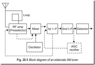
Fig. 28.5 depicts the block diagram for an elaborate AM tuner. This arrangement employs five transistors, a diode detector, and a diode a.g.c. rectifier. Reception is provided by a built-in loop, which may be supplemented by an external antenna, if desired. The incoming signal is stepped up by a preselector stage, followed by a mixer-oscillaor section for frequency conversion. The first i.f. stage is a.g.c. controlled. This transistor does double duty in that it provides i.f. amplification and also operates as an amplifier for a.g.c. current. Thus, amplified a.g.c. current is applied to the r.f. amplifier transistor. The mixer transistor is biased by a.g.c. current that has been amplified through the r.f. amplifier transistor.
PRACTICAL AM TUNER CIRCUIT
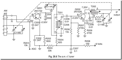
Fig. 28.6 illustrates the circuit of a broadband a.m. broadcast band tuner. The a.m. r.f. amplifier transistor, Q201, is a 2N1732 in a common-emitter circuit. The ferrite-rod antenna shown at the extreme left on the schematic is tuned by one section of the three gang a.m. tuning capacitor (C118D). A common trouble with a.m. tuners is a broken antenna loopstick. Should the ferrite rod become cracked, the receiver will tend to exhibit low a.m. sensitivity.
The r.f. signal from the antenna is coupled to the base circuit by the few-turn secondary winding (marked H in schematic). This provides for an impedance match to the r.f. amplifier base circuit. Automatic gain control is applied to the base by means of resistor R201. Transformer T201 provides for selective coupling and impedance matching from the collector of the r.f. amplifier to the base of the converter transistor (Q202), the local oscillator and mixer stage.
The supply voltage for the tuner circuit may be provided by a small “transitor radio” type battery (9 V) but the circuits themselves are more or less basic in nature, and variations of them are to be found on units that employ their own integral dc power supplies driven from commercial ac mains.
FM TUNERS
FM tuners operate in the very high-frequency regions and consequently have operating requirements different from those of a.m. tuners. The r.f. circuits and components must be of optimum design to provide sufficient sensitivity to pick-up f.m. stations under all conditions, and the audio aspects all circuitry must be of sufficient quality of design and construction to receive and pass audio frequencies from 15 to 20 kHz as may be broadcast by f.m. stations.
High fidelity AM reception is usually limited by the presence of high-level man-made noise and atomospheric disturbances which AM receivers cannot reject without loss of fidelity. Also, because of the propagation characteristics of frequencies used for standard a.m. broadcasting, out-of-area broadcast station signals can interfere with local reception (especially at night). At the frequencies used for FM reception, distant stations cannot interfere, and the inherent noise-rejection characteristics of the FM receiver minimise the noise problem.
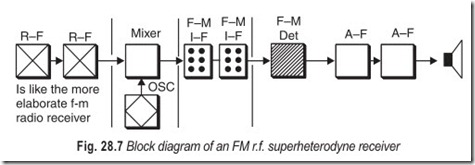
Receivers for frequency modulation are of the superheterodyne type and are somewhat similar to ordinary amplitude modulation superheterodynes. Block diagram of the most widely used FM receiver is shown in Fig. 28.7. The most important difference between AM and FM receivers is in the detector circuit. A number of FM detectors have been developed. The ratio detector removes the audio signal from the carrier and at the same time rejects amplitude impulses which may accompany it. The Foster-Seeley discriminator is sensitive to amplitude impulses and in order to eliminate them before detection, limiter stages must be provided. The limiter removes all amplitude fluctuations from the carrier before if is applied to the detector.
Practically all current f.m. tuners are transistorised. Many FM tuners are combined with AM (AM/FM) tuners. Superheterodyne configuration is universal; however, considerable variation of detail is employed. For example, low priced FM tuners used a single transistor as a combined oscillator and mixer (converter), whereas deluxe type tuners provide separate oscillator and mixer transistors. Again, economy-type designs generally utilise ganged tuning capacitors, while the more elaborate designs provide permeability-tuned arrangements. Solid-state designs are based on the transistor-for-tube principle, except for systems employing IC packages.
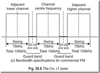
An f.m. broadcast signal is basically a high fidelity transmission, whether the mono or the stereo mode is used. The high fidelity capability of an FM. system is due to its comparatively wide channels. Each FM broadcast channel has a bandwidth of 150 kHz, or + 75 kHz. Although a high fidelity FM signal can be transmitted in a narrower channel, wide channels provide a better signal to noise ratio.
It follows that an f.m. receiver should have a bandwidth of 150 kHz. The f.m. broadcast band extends from 88 to 108 kHz, and f.m. station occupies (including its guard band) a range of 200 kHz. Thus, a maximum of 100 FM broadcast stations can be accomodated in a given service area. Co-channel interference from distant areas is much less troublesome in the case of f.m., than for f.m. This comparative immunity of an FM receiver to co-channel interference is due to he “capture effect”, which means that the stronger signal tends to suppress the weaker signal. If one signal is twice as strong as the other signal, the suppression is practically complete. Even if one signals is only 50 per cent stronger than the other, the suppression is very effective, provided that the receiver is properly adjusted.
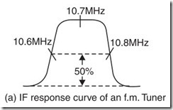
All f.m. receivers use an intermediate frequency of 10.7 MHz. At the 50 per cent of maximum response points (6 dB down) on the i.f.
response curve, the bandwidth is typically 200 kHz, as shown in Fig.28.8 (a). The comparatively high value of intermediate frequency reduces the circuit complexity that is required. If a lower intermediate frequency, such as 455 kHz, were used, elaborate circuitry could be required to obtain a flat-topped response over a bandwidth of 150 kHz. When the bandwidth of an amplifier is increased, its gain is decreased. Therefore, the i.f. stage gain is considerably less in an f.m. receiver than in an a.m. receiver. Therefore, an f.m. receiver employs more i.f. stages. At least one more i.f. stage is provided in most tuners. When two more f.m. i.f. stages are included, the last stage operates as a limiter; since the limiter is essentially an overdriven amplifier, its gain is considerably less than that of the other i.f. stages.
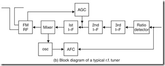
The block diagram of a typical f.m. tuner is shown in Fig. 28.8 (b) and bandwidth specifications for commercial f.m. in Fig. 28.8(c). Some FM tuners employ integrated circuitry. When an IC section develops a defect, the terminal voltages become abnormal in most cases. This situation is analogous to abnormal terminal voltages for a defective transistor.
PRACTICAL FM TUNER CIRCUITS
1. FM Tuner Using BF200 Silicon Planar Transistors: High quality FM reception calls for a tuner having a low noise factor and excellent signal handling ability. These objectives can be achieved by exploiting the inherently good signal-handling capability of the BF200 in a circuit configuration favouring optimum noise performance.
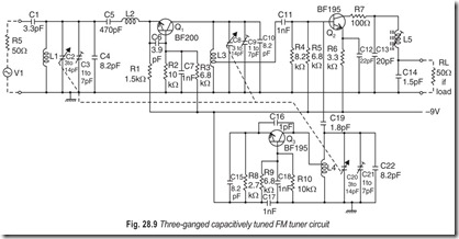
This high-performance tuner uses a tuned aerial circuit matched to the r.f. transistor by a fixed inductance. By this means it is possible to retain the benefits of a low-loss selective aerial circuit, which can be approximately power matched, and, through an impedance transform, to allow the transistor to be matched for optimum noise performance. The transistor is then required to handle less signal for a given noise performance. The complete circuit of a three-ganged capacitively-tuned f.m. tuner is given in Fig. 28.9.
RF Stage : The BF200 transistor, Q1 operates in the common-base configuration at a collector current of 2 mA. The optimum source impedance for minimum noise is equivalent to the parallel combination of 125 Ω resistance and 500 µH inductance, giving a typical noise factor of 2 dB.
The emitter resistor R1, inductance L2 and capacitor C6 cause some additional losses which result in a typical noise factor for the tuner of about 4.5 dB. Capacitor C6 prevents parasitic oscillations at very high frequencies and must be mounted between the base and emitter leads of the BF 200 and as closely as possible to them.
The low feedback capacitance of the BF200 allows the collector to the top of the tuned interstage circuit. The collector output damping of the BF200 is negligible.
The transducer gain of the r.f. stage is about 16 dB at a 3 dB bandwidth of the loaded interstage circuitof 1 MHz. The value of Q0 of this tuned circuit is 200.
Mixer Stage : The mixer transistor, Q2 is a lockfit transistor, type BF 195, and operates in the common emitter configuration at a collector current of 1 mA. At this current and with a source impedance of about 100 Ω, the contribution of the mixer stage to the total noise factor is small—approximately 0.5 dB.
By keeping the oscillator signal at the base of Q2 to as low a value as possible—about 50 m V-harmonics of the oscillator frequency at the input to the mixer are virtually eliminated, while sufficient conversion gain is maintained.
Because the base of Q2 has an inductive tap on the interstage circuit, no additional 10.7 MHz. i.f. seriesfilter is necessary between the base and the emitter. To prevent i.f. parasitic oscillations a 100 Ω resistor, R7, is connected in series with the collector. The value of Q0 of the i.f. tuned circuit is about 150. The mixer gain is about 18 dB.
Oscillator : The oscillator transistor, Q3 is a also aBF 195, and operates in the common-base configuration at a current of 1 mA. The coupling between the top of the oscillator coil and the base of the mixer is obtained via capacitor C19. The low value of this capacitance—1.8 pf-guarantees that large aerial signals have practically no effect on the oscillator circuit. The oscillator frequency is below the aerial frequency.
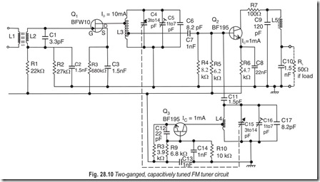
1. FM Tuner Using BFW-X 10 Field-Effect Transistor : The circuit for a high-quality, two ganged, capacitively-tuned FM tuner is shown in Fig. 28.10. The tuner uses a BFW 10 field-effect transistor in the r.f. input stage, and BF 195 transistors in the mixer and oscillator stages.
RF Stage : The BFW 10 field-effect transistor operates at a typical drain curent of 10 mA and typical drain-source voltage of 6 V. The optimum source impedance for minimum noise is equivalent to the parallel combination of 910 Ω resistance and 370 µH inductance, giving typical noise factor of 2.5 dB.
The aerial input circuit is transformer—coupled to the input of the field-effect transistor, the unloaded quality factor, Qo, of the aerial transformer being about 80 at a secondary inductance of 330 µH.
The transducer gain of the r.f. stage is about 8.5 dB at 100 MHz. The value of Qo for the interstage circuit is 200.
The dc stabilisation is obtained by a voltage divider from the gate electrode and source resistance of value 680 Ω. A limitation of this design is that the minimum value of IDSS for the field-effect transistor is 8 mA, because the gate of the transistor may not be positive with respect to the source.
Mixer and Oscillator Stages : Comparison of the circuit diagram of this tuner with that of the planar transistor version shown in Fig. 28.9 will show that the mixer and oscillator stages of the two circuits are almost identical.
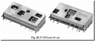
A comparison of the two tuners will reveal that the circuits give very similar performances. However, it should be noted that the FET tuner achieves this performance at the expense of a relatively high supply voltage and high operating current in the r.f. stage. In addition, the field-effect transistor must be selectedfor a value of IDSS ( drain current at zero source-gate voltage) of 8 to 20 mA. Typical AM/FM tuners are depicted in Fig. 28.12.
(i) Excellent performance enabled by MOSFET at RF AMP and JFET at OSC stages
(ii) Compact design incorporating chips for high fidelity
(iii) Satisfies FCC regulations
(iv) Superior performance with DBM IC, high power gain, excellent beat characteristics
(v) Compact design incorporating chips for high fidelity
(vi) Stable DSC DRIFT effected by large signal + B voltage.
Crystal-controlled FM Tuner Design :An ideal tuner must be sensitive and selective, have good spurious and image rejection, have good capture ratio, and provide recovered audio with low distortion. Since low distortion is achieved only when the r.f. signal is properly tuned, low drift is essential to maintain this condition. For operating convenience, a method of station pre-selection as well as the ability to scan should also be available. The readout accuracy should be such that there is absolutely no doubt as to which frequency or channel is being received. Manual fine tuning to reach the centre or low distortion point of a signal should be eliminated because mistuning is probably the greatest source of distortion in FM reception.
The most obvious and simplest solution to eliminating fine tuning of the oscillator is to use a crystal- controlled oscillator. Since the oscillator frequency is always 10.7 MHz above the receiving frequency 100 crystals covering from 98.8 MHz to 118.6 MHz in 200 kHz steps would be required for all channels. A 100- position rotary selector switch would serve as a tuning knob and provide a mechanical or electrical readout determined by its shaft position. This system effectively eliminates the need for fine tuning but is far too expensive. Using frequency mixing techniques, it is possible to bring the number of crystals down to 20 for dual conversion and 15 for triple conversion but the additional switchable filter requirements also make this approach expensive. Furthermore multi-conversion designs may be troubled by spurious response and poor image rejection performance due to the nonlinearity of the mixer circuits.
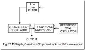
The Crystal Oscillator : The oscillator of digital FM tuner is crystal controlled on every frequency but uses only a single quartz crystal as a reference standard. This is accomplished by making the oscillator part of a digital phase locked loop (PLL) circuit. In order to understand this principle, let us look at the simplest PLL circuit which locks an oscillator to a reference frequency.
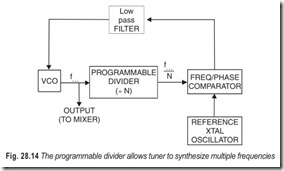
When the system shown in Fig. 28.14 is first turned on, the voltage-controlled oscillator frequency will not be exactly the same as the reference frequency. The output of the frequency-phase comparator is an error voltage which tunes the VCO in a direction to minimise the error until phase-lock condition is established and fosc = fref. Since the control voltage for the VCO is ideally a dc voltage, the low-pass filter is used to remove any high frequency components which might be present at the output of the comparator.
In order to generate a large number of frequencies from a single reference, a programmable divider is inserted into the PLL as shown in Fig. 28.14. The loop behaves as before except that a submultiple of the VCO is now presented to the comparator and the frequency relationship becomes.
fosc /N = fref
fosc = Nfref
Stations are assigned to fall on 100 channels from 88.1 to 107.9 MHz inclusively with a spacing of 200 kHz. Since the channel spacing requirement is 200 kHz, the reference frequency of the crystal oscillator must be 200 kHz if its multiples are to fall on each FM channel plus 10.7 MHz. Let us calculate what the divide ratio must be when the tuner is receiving 88.1 MHz or the bottom channel on the band.
The oscillator frequency will be 88.1 + 10.7 = 98.8 MHz. Substituting into the earlier equation to find the divide ratio N:
N = fosc / fref = 98.8/0.2 = 494
This means that the voltage-controlled oscillator will be at a frequency of 200 kHz multiplied by 494 or
98.8 MHz. The next channel higher at 88.3 MHz will require a divide ratio of 495 and so on until 107.9 MHz, the top of the band, is reached at a divide ratio of 593.
For the tuner to scan the entire FM band, the programmable divider must therefore be able to divide from 495 to 593 inclusively.
Consequently every time a new station is desired, the divide ratio must be altered. Since several IC counters are available with a variable modulo or programmable count sequence, one of these is used here.
The divide ratio is altered by inserting a binary code which affects the length of the count sequence and hence the divide ratio. Each channel or frequency requires a unique code which is presented to the divider.
The code itself is derived electronically and can be generated in a sequence which will make the tuner appear to scan across the FM band. It actually “steps” across the band rather than scans continuously since it only pauses (phase locks) on assigned channels. The tuner can also be tuned or programmed by cards which present a binary code to the code generator which in turn decodes it and passes it on to the programmable divider. The card system overrides the other forms of sequential tuning and allows instantaneous preselection of stations by using the desired card.
Digital Frequency Readout : The tuner uses the familiar cold cathode neon indicator tubes which were chosen for reliability, long life and reasonable cost. The display is actuated by the same binary code which the code generator supplies to the programmable divider to set its divide ratio. Aside from displaying the frequency in MHz which the tuner is receiving at any given moment, the display serves as a self-checking feature for the code generator as well as the card reader. The binary code from the code generator is decoded into decimal form and used to drive the display; if an incorrect or non-allowable code its presented to the divider such as one caused by a damaged card, the readout will immediately show the error.
The digital readout in the tuner is not simply hooked up to a frequency counter which counts the oscillator frequency minus 10.7 MHz. The frequency counter is a “passive” addition which will work with any existing tuner while the PLL design is an “active” system which requires an electronically tuned r.f. section. In the passive system, manual fine tuning is still required. With a PLL system the oscillator is forced to lock at each channel centre, which always falls exactly on the assigned frequencies of the broadcast stations.
The digital PLL system provides an r.f. oscillator of crystal stability on all frequencies plus an absolutely accurate digital display of the frequency being received. The binary code generator setting the divide ratio allows the operator to scan the FM band manually at a preselected speed or to let the circuit search for a station or stereo station automatically. If one station of known frequency is desired, a pre-punched card can be used to tune to it immediately.
This feature will appeal to the discriminating music listener who has a small number of favourite stations and selects definite programs. The scan feature on the other hand might appeal to the less critical listener who usually scans the band until he hears something he likes.
Other Features : One of the extremely useful by-products of this system is automatic interstation muting. The tuner just won’t time between channels. Noise muting is also provided however for silencing empty channels; this type of muting is defeated by a front panel switch. During the automatic “Stereo Station” scan mode, all mono stations are muted. When tuning from one station to another regardless of which tuning mode is used, the sound disappears without the usual transient swish or thump and reappears out of complete silence again with the absence of annoying noise bursts and distortion.
All muting is done after the multiplex decoder by two FET series-gate switches which reduce the signal by at least 60 dB in the muted condition without introducing a dc transient.
The r.f. section in the tuner employs selected high-gain, low-noise FET’s for both r.f. gain and mixer functions. A FET is also used for impedance matching and low noise in the first stage of the i.f. amplifier. Two 6-pole elliptical filters shape the passband of the i.f. and achieve a selectivity in excess of 70 dB which allows this tuner to select any one station from a crowded area on the band.
The “station” light on the front panel indicates the presence of a carrier and its actuated by a zero- crossing detector coupled to the output of the ratio detector; the station light is also a double check on the PLL and reference standard because it is actuated only if the station is tuned to exact centre. On noise which is present on empty channels, the station light is extinguished automatically. The “stereo” indicator will light up in the presence of a 19 kHz subcarrier when the signal level is sufficient to give an acceptable signal to noise ratio. A “card program” indicator shows at a glance whether or not card tuning is being used. Aside from providing instantaneous preselection of station frequencies, the card serves as a permanent memory since the code generator’s volatile memory loses the station code when power is turned off.
Trend to Complexity : The trend in consumer electronics is toward greater circuit complexity made possible at low cost due to the use of integrated circuit technology. The circuit designer gains flexibility in achieving performance goals and operating convenience for the customer. Unless proper steps are taken, however, servicing of this type of equipment can become a problem as troubleshooting time and test equipment expenditures increase drastically.
The best approach seems to centre around modular construction with each module representing a functional sub-assembly which can be replaced with no more effort than the vacuum tube in an old TV set. Fault location is greatly simplified by the fact that each module performs a definite function which can be monitored individually with a minimum of test instruments.
Once the faulty module is replaced by the service shop, it is sent back to the factory where automated test facilities localise the fault to a component on the sub-assembly and it is either repaired or scrapped. This module exchange policy has been used for some time and is gaining in importance as equipment complexity increases. The customer also has the advantage of knowing exactly how much the repair will cost if it is done after the warranty period has expired because definite module exchange prices have been established. Even service shops with limited facilities can repair a unit as complex as the digital FM tuner if a set of PC modules or even another operating unit is available. Each module is simply interchanged with a new one until the fault disappears.
Although the complexity of circuitry has increased, reliability has increased also. Through the use of MSI (medium scale integration), the number of hard-wired interconnections has actually decreased thus avoiding a significant number of failures. By screening IC’s in incoming inspection, testing assembled modules under worst case conditions before they are mounted into complete units, and extensive life testing of finished products, the failure rate has been reduced to a fraction of what it was a few years ago. The IC’s used as building blocks in the digital sections are of the standard variety already well proven in the computer industry and second sourced widely.
EXERCISES
Descriptive Questions
1. What are the requirements of an r.f. tuner?
2. Compare a.m. with f.m.
3. Explain the working of a tuner with the help of a block diagram.
4. Differentiate between a.m. and f.m. tuners.
5. How does a PLL system work?
6. What are the advantages of modular construction?
Multiple Choice Questions
1. In AM
(a) the phase remains constant (b) the amplitude remains constant
(c) the frequency remains constant (d) none of the above
2. In FM
(a) the amplitude remains constant (b) the phase remains constant
(c) the frequency remains constant (d) none of the above
3. The intelligence to be transmitted usually consists of an audio modulating signal with frequencies in the range
(a) dc to several MHz (b) 20 Hz to 20 kHz
(c) 20 kHz to 20 MHz (d) dc to 20 Hz
4. The modulating signal is superimposed upon the radio frequency carrier by applying both to a
(a) linear impedance (b) complex impedance
(c) non-linear impedance (d) none of the above
5. The resulting modulated wave consists of
(a) the original carrier frequency (b) sum of frequencies
(c) difference of frequencies (d) only (b) and (c)
6. The width of the band is determined by
(a) the carrier frequency (b) the lowest audio frequency
(c) the highest audio frequency (d) none of the above
7. In FM the amount of variation from the carrier frequency is called
(a) depth of modulation (b) frequency deviation
(c) guard band (d) modulation index
8. Frequency deviation can be
(a) positive (b) negative
(c) both (a) and (b) (d) either (a) or (b)
9. The FCC defines 100 per cent FM modulation as
(a) + 15 kHz deviation (b) + 25 kHz deviation
(c) + 50 kHz deviation (d) + 75 kHz deviation
10. The AM station may transmit audio frequencies upto
(a) 2.5 kHz (b) 5 kHz
(c) 7.5 kHz (d) 10 kHz
11. The FM station may transmit audio frequencies upto
(a) 15 kHz (b) 7.5 kHz
(c) 5 kHz (d) 2.5 kHz
12. The bandwidth of an a.m. signal is
(a) directly proportional to the frequency of the modulating signal
(b) indirectly proportional to the frequency of the modulating signal
(c) not related to the frequency of the modulating signal
(d) 10 kHz
Fill in the Blanks
1. Tuners are available to receive AM or FM signals ……………………………. or in one……………………………. unit.
2. FM tuners can provide a greater range of……………………………. and high fidelity over the entire FM range.
3. An AM tuner is a……………………………. version of a conventional AM radio receiver but without an audio amplifier and……………………………. .
4. In most cases a hi-fi a.m. tuner is provided as a section of a hi-fi a.m/f.m.……………………………. .
5. The superheterodyne configuration is……………………………. although design details ……………………………. considerably.
6. Deluxe a.m. tuners are provided with at least one stage of……………………………. to improve selectivity and image rejection.
7. At the frequencies used for f.m. reception, distant stations cannot……………………………. .
8. The most important difference between a.m. and f.m. receivers is in the……………………………. circuit.
9. The limiter removes all……………………………. fluctuations from the carrier before it is applied to the……………………………. .
10. Economy-type tuner designs generally utilise……………………………. tuning capacitors.
11. Elaborate type tuner designs generally employ……………………………. tuning.
12. Wide channels provide a better……………………………. ratio.
13. Capture effect means that the stronger signal tends to……………………………. the weaker signal.
14. When the bandwidth of an amplifier is increased its gain is……………………………. .
15. An ideal tuner must be……………………………. and selective.
16. Multiconversion tuner designs may be troubled by spurious response and poor image rejection performance due to the……………………………. of the mixer circuits.
17. Every time a new station is desired the divide ratio must be……………………………. .
18. The PLL design is an……………………………. system which requires an electronically tuned r.f. section.
ANSWERS
Multiple Choice Questions
|
1. (c) |
2. (a) |
3. (b) |
4. (c) |
5. (b) and (c) |
6. (c) |
|
7. (b) |
8. (a) and (b) |
9. (d) |
10. (d) |
11. (a) |
12. (a) |
Fill in the Blanks
|
1. separately, combined |
2. reproduction |
3. refined, speaker |
|
4. receiver |
5. universal, vary |
6. pre-selection |
|
7. interfere |
8. detector |
9. amplitude, detector |
|
10. ganged |
11. permeability |
12. signal-to-noise |
|
13. suppress 16. nonlinearity |
14. decreased 17. altered |
15. sensitive 18. active |

