Before talking about how various emissions are controlled, it would be well first to describe what these emissions are and wher e they come from.
First, there are unburned hydrocarb-ons. These are simply unburned gasoline. They appear in four areas, each of which has to be controlled separately. These are the engine orankcase, the exhaust, the caJ1buretor and the gasoline tank. Emissions from the crankcase are handled by the crankcas e ventilation system, already described.
Hydrocarbons normally are harmless and in visible, but when held in suspension and sub jected to sunlight, can combine with oxides of nitrogen to form photochem ical smog. In heavy concentra tion this smog will cause irritation to the eyes and nose. Control of emissions from the car buretor and gasoline tank will be described later.
Second, there is the ‘actual exhau st gas, which consists m ainly of carbon dioxide and water, which are harmle ss; carbon monoxide, which is deadly; oxides of nitrogen, which, if not dangerous, do appear to be objectionable, as they cause the smog that brings eye smarting. And there is ·also a cer tain amount of unburned hydrocarb ons in the ex haust .
Carbon dioxide ( C02 ) and water are the nor mal result of burning a mixture of gasoline and air. Carbon monoxid e (CO) and the unburned hydrocarbons in the exhaust are the result of in complete combustion of gasoline and air. They can be removed, or transform ed into C02 and water by additional burning-by adding extra air while they are still very hot; by slowing down th e burning in the cylinder so that they have more time to burn before being expelled; or by p assing hem over a catalyst in a special muffier where they are persuaded to combine with more air and become harmless. This latter method is at this time, being studied extensively by vehicle manu facture.l’S.
Oxides of nitrogen can be reduced but not eliminated, by reducing the temperature of combustion in the cylinder, but that increases carbon monoxide and hydrocarbon emissions. And they can be re duced by lowering the compression ratio (which also reduces cylinder temperature). But all this reduces power output. In fact the methods of con trolling exhaust emissions are changing very rap idly.
The sealed crankcase, which wa>s the first step in reducing automotive emissions, came in 1961-62. Since then new steps have been added each year, and it seems probable that further changes will ap pear regularly for some time to come until the emissions are reduced to acceptable amounts.
Basically two methods are being used to reduce unburned hydrocarbons and carbon monoxide in the exhaust. The first to be developed and now gradually dropping from favor, is the air pump method. It is used by all maker’s and involves the use of a special air pump which forces air through jets into each exhaust port to provide extra oxy gen so that the noxious gases can be burned up. In addition to the air pump, there are several valves to control and direct the air and a number of hoses to conduct the air to the desired locations. This system seems to be the most effective.
The second method involves burning the noxious gases in the cylinders. It was initiated by Chrysler and refinements of it are now used by all makers on most models. It accomplishes its purpose by using a much weaker than normal idle mixture and a retarded spark at idle. (It’s at idle speed and during deceleration that emissions are greatest.) As far as it goes neither method is 100% effective. This, of course, is a great over-simplification of the method, but it will be described more fully later on.
Some of the refinements that have been added to the second method include special valves to control vacuum to the distributor advance mecha nism, specially calibrated carburetors with idle mixture adjustment stops to prevent over-enrich ment, thermostatically controlled engine air in takes, and higher temperature coolant thermostats. In addition, as new engines are designed especially to reduce emissions, the bore to stroke and com pression ratios are reduced. To overcome the loss of efficiency resulting from these changes, engine displacement is being increased in turn increasing fuel consumption.
ELECTRIC ASSIST CHOKE
Most 1973-77 American Motors, Chrysler, Ford and General Motors vehicles are equipped with an electric assist choke. Cadillac models with fuel in jection incorporate a fast idle valve which is elec trically controlled and serves the same purpose as the choke. This device aids in reducing the emis sions of hydrocarbon ( HC) and carbon monoxide (CO) during starting and warmup (choke on) pe riod. The electric assist choke is designed to give a more rapid choke opening at temperatures of about 60° to 65° F. or greater and a slower choke opening at temperatures of about 60° to 65° F. or below.
The electric assist choke system does not change any carburetor service procedures and cannot be adjusted. If system is found out of calibration the heater control switch and/or choke unit must be replaced.
American Motors & Ford
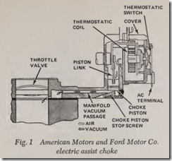
The electric choke system, Fig. 1, consists of a choke cap, thermostatic spring, a bimetal tempera ture sensing disc (switch), and a ceramic positive temperature coefficient ( PTC) heater. The choke is powered from terminal or tap of the alternator. Current is constantly supplied to the ambient tem perature switch. The system is grounded through a ground strap connected to the carburetor body. At temperatures below approximately 60 degrees, the switch opens and no current is supplied to the ceramic heater located within the thermostatic spring. Normal thermostatic spring choking action then occurs. At temperatures above approximately 60-65 degrees, the temperature sensing switch closes and current is supplied to the ceramic heater. As the heater warms, it causes the ther mostatic spring to pull the choke plates open within 1-B minutes.
General Motors
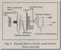
The main components of the electric assist choke system, Fig. 2, consist of the thermostatic coil, ceramic resistor, cover, bi-metal snap disc and contact spring. The ceramic resistor is divided into a small center section for gradual heating and a large outer section for rapid heating of the ther mostatic coil. The electric actuated ceramic re sistor heats the thermostatic coil, gradually relax ing coil tension and allowing the choke valve to open.
At air temperatures below 50° F., electric cur rent applied to the small section of the ceramic resistor, allows slow opening of the choke valve f or good engine warm-up. As the small section of the ceramic resistor continues to heat, a bi-metal disc causes the spring loaded contact to close and apply electric current to the large section of the ceramic resistor which increases the heat flow to the ther mostatic coil for more rapid opening of the choke valve.
At air temperatures between 50-70° F., electric current applied to the small section, or both the small and large sections of the ceramic resistor, will produce the amount of heat requir ed to con trol the choke valve position for good engine operation in these temperature ranges.
At air temperatures above 70° F., electric cur rent applied to the small section of the ceramic resistor and through the spring contact to the large section of the ceramic resistor, provides rapid heating of the thermostatic coil for quick er choke valve opening when leaner air/fuel mixtures are required at warmer temperatures.
For operation and servicing of the fast idle valve, refer to the “Fuel Injection Section”.
Chrysler
NOTE: The wattage of the choke heater is pa rt of the choke calibration and may change from year to year.
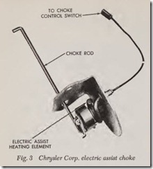
The control switch, Fig. 3, is connected to the ignition switch from which electrical power is obtained and transferred through electrical connection to the control switch. The 1973 switch
serves two purposes:
1. Above 63° F. the control switch will energize the choke heater.
2. After a period of time, the control switch will de-energize the choke heater. The shut-down will result after the control switch warms to about 110° F. by engine heat and a small electrical heater within the switch. Since the heater control switch is mounted to the engine and near the carburetor, some winter opera tion may energize the choke heater. This could happen after the choke has opened without b enefit of electric heat. If this happens it will have no adverse effect on engine operation, and will soon be turned off.
The 1974 control switch serves three purposes:
1. Below 58° F. the control switch will partially energize the choke heater.
2. Above 58° F. the control switch will fully en ergize the choke heater.
3. The control switch will de-energize the choke heater at approximately 110° F. During winter operations , engines will experience three stages of choke heat: partial heat during en gine warm-up, full heat after engine warm-up and no heat well after engine warm-up. Engine starts during summer temperatures will not experience the partial heat stage.
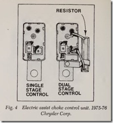
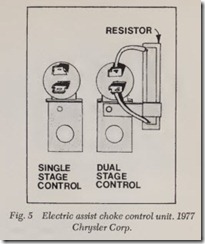
Two different control switches are used on 1975-77 vehicles: a single stage unit and a dual stage unit, Figs. 4 and 5.
The 1975-76 single stage control switch serves two purposes:
1. Above 68° F., the control switch will energize the choke heater.
2. At about 130° F., the control switch will de energize the choke heater.
Since the control switch is engine mounted, some cold engine operation may energize the choke heater, especially if the choke valve has been opened without electric heat. This condition which has no adverse effect on engine operations, will return to normal.
The 1977 single stage control switch shortens choke duration only above 80° F. Below 55° F., electric heat is not available until the engine is at normal operating temperature. Normal engine heat will then warm the control and energize the choke heater, but only after the choke has opened by engine heat.
The 1975-76 dual stage control switch serves four purposes:
1. Below 58° F., the control switch will partially energize the choke heater.
2. Between 58-68° F., the control switch will either partially energize or fully energize the choke heater.
3. Above 68° F., the control switch will fully energize the choke heater.
4. At about 130° F., the control switch will deenergize the choke heater.
The 1977 dual stage control switch shortens choke duration above 80° F. and stabilizes choke duration during cold weather operation. During hot weather operation, electric assist heat is hotter
than during cold weather operation assist level.
Cold weather heat levels are regulated by an electrical resistor connected to both terminals of the control. Below 55° F., electrical power is re duced by the resistor. Above 80° F., the resistor is bypassed by a switch inside the control to supply full power.
Engines started during cold weather conditions will experience two levels of choke heat : low dur ing engine warm-up and high after engine warm up. High heat levels occur after the choke is open to insure an open choke condition under all driv ing conditions and to minimize chokin g action which can occur after short stops during cold weather operation.
Engines started in hot weather conditions will not experience low choke heat levels. Engines started hot will only experience high heat because the switch is normally warmer than 80° F.
NOTE: The heating element should not be ex posed to or immersed in any fluid for any purpose. An electric short in the wiring to the heater or within the heater will be a short of the ignition system.
CHOKE HOT AIR MODULATOR
General Motors
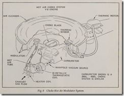
All 1975-77 Buick V6-231, V8-350 and V8-455,
Oldsmobile Omega and Starfire V6-231 and V8- 350 and Pontiac Ventura and Sunbird V6-231 and V8-350, incorporate a choke hot air modulator lo cated in the bottom of the air cleaner housing to provide heated filtered air to the choke housing, Fig. 6. When air cleaner temperature is below 68° F., the air heated by the heater coil will pass through a .005 inch orifice in the modulator, allow ing very little hot air flow over the bi-metallic thermostatic coil and providing slower choke warm-up. Above 68° F. air cleaner temperature, the modulator opens, allowing more air flow and f aster choke warm-up.
